I know it's not working because is not complete 🙂
as you can see the input of the last 2 lm3886 at the bottom is on (pin 9 Vin -) unlike to the two LM3886 at the top of the diagram is on Pin 10 (vin +).
I just need partial assistment of the schematic.
as you can see the input of the last 2 lm3886 at the bottom is on (pin 9 Vin -) unlike to the two LM3886 at the top of the diagram is on Pin 10 (vin +).
I just need partial assistment of the schematic.
No that's not what I meant. I understood that it's not complete and I saw that the 2 on the bottom is connected to Vin-.I know it's not working because is not complete 🙂
as you can see the input of the last 2 lm3886 at the bottom is on (pin 9 Vin -) unlike to the two LM3886 at the top of the diagram is on Pin 10 (vin +).
I just need partial assistment of the schematic.
But it is still faulty. The speaker is not connected as it should be. Also, your Rf and Ri-resistors are not correctly connected. And Ri has not a good value.
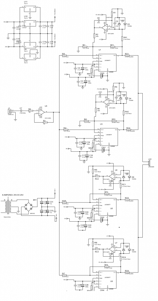
Incorrect polarity of the negative rail bypass caps (C2.....) and the mute caps.
Thank for comment
-the MUTE caps is 10uF Caps Part Reference in schematic CIN1,CIN2,CIN3,CIN4 is connected to pin 8, and 7 of LM3886TF, Pin7(GND).
-C2,C16,C22,C26 Filter caps value 1000uF/50v is connected to -35V input of LM3886TF Pin(4) V-
I can't see any Incorrect polarity.
Thanks
Last edited:
All the above mentioned capacitors are drawn the wrong way round. Compare them to C32-C33.
It should be Cm (Cmute) instead of CIN.
It should be Cm (Cmute) instead of CIN.
I need a third the opinion about the capacitor polarity in my diagram.
by the way sir I designed that schematic using isis proteus.
thanks for comment
by the way sir I designed that schematic using isis proteus.
thanks for comment
okay I recap again my schematic, your comment is helping me a lot to make my diagram more accurate.
You need to understand what you are designing and how it works. Not rely on others to fix your mistakes. The schematic is the easy part, a good PCB is far more difficult to design.
I know, sir but I believe that the polarity of the capacitor you mentioned earlier that wrong, is correct; that's why I need the opinion of others, I accept it if someone also say that the polarity of my capacitor is wrong, but again I review it again.and what is the purpose of forum if I the only one who answer my questions;
here my another recap of my schematic; I never change the polarity of the capacitor in mute and in-35v bcoz I believe the polarity is correct; but I made some change of the resistor value
here my another recap of my schematic; I never change the polarity of the capacitor in mute and in-35v bcoz I believe the polarity is correct; but I made some change of the resistor value
Last edited:
It's already 2am here in Philippines when I designing this diagram 🙂
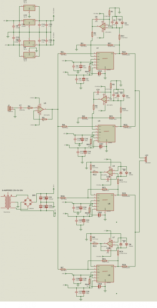
here the corrections:
Thanks for the corrections you helping me a lot.
here the corrections:
Thanks for the corrections you helping me a lot.
I seem to recall having chipped in as well. Oh, well. I guess he'll learn. Or not... 🙂 
There are numerous errors on the schematic. The most obvious one is that half the local decoupling caps are polarized the wrong way. You can't just put two LM78L15/LM79L15 in parallel to get twice the current. At least use ballasting resistors. Or ... just use the 500 mA or 1 A version of the regulator.
My suggestion:
1) Build the power supply first. Get it to work. Test it with a load resistor.
2) Build one (1) channel of the amp without DC servo. Get it to work. Test it.
3) Add DC servo. Get it to work. Test it.
4) Build a second channel with DC servo. Get it to work. Test it.
5) Connect the two channels together either bridged or parallel. Test the resulting amp.
6) Etc.
Build in blocks, test the blocks, then combine them to form larger circuits. All experienced designers do this - either in the simulator or on the bench.
There. I've led the horse to water. It's up to him to drink it.
~Tom
Once you start laying out the board you will find that using a Quad opamp won't save you any board space at all.
Maybe when using the LM4780's a dual opamp type might work Okay.
But then there is also the issue of finding a dual or quad type that has the voltage offsets (Vos) perfectly matched as per section.
I have not had good luck with some of the common dual types I have tested so far.
This increases the cost of having to use some more expensive precision types that are guarantied very low Vos per section.
Then there is the issue of routing power to the servo opamps.
For this I have been looking at some high voltage types that seem to have very good Vos spec's as well.
There are actually only a few that can be chosen from in this category and they are not quad types.
But this would allow the use of the common power supply bus without the complications of regulating sections and their associated extra parts and boards space.
I know this from trying to design my own BPA an PA setups using multiple chipamps.
I am having to also possibly revert to some non common methods of construction using several layered boards to make everything fit in a nice compact area with low inductance traces.
This cannot happen if one uses a quad opamp type for the servo's to be used among all of the four sections laid out lengthwise.
They will for certain have to use very long traces to connect them, and this will effect or even defeat the performance that one has originally set out to get.
I am trying to follow tomchr's and AndrewT's (as well as others) suggestion's in their threads showing proof of how very important it is to keep the traces as short as possible while watching out which way the return currents are going.
The information they have taken the time to show and discuss is priceless after I have been following such designs for the better part of the last 10 years!!
Granted, I have yet to build a actual chipamp using the LM3886's and LM4780's, and after watching many with just as much experience as myself at building circuits (if not more), I have seen them struggle with them as well.
The very First one I have designed and made just recently uses a LT1210 with a LT1007 for the servo and it worked the very first time I threw it together.
But, As I got to using and messing with it, The circuit started to grow and grow as I had to work out a few issues of instability along the way.
This amp is good for as high as 30Mhz!!
That is just for making one section and getting it to work properly, as my plan was to make a few of them to parallel up as well!!
I am not trying to deter you from your goals.
But, It is much more complicated than just copying a schematic from the data sheet and making mistakes doing so along the way doesn't help in any way either.
One of the biggest issues I have had watching these threads is trying to follow revision after revision of finally getting one to work properly with much satisfaction in the final design, mostly do to typo's or missing parts in their design!!
But, Ya gotta love R&D besides!! 😉
I completely agree with the guys when they say build one section and then add the servo or composite opamp or whatever technique you chose to use, First!!
Then start paralleling the working sections while working out the issues everytime you add one.
Then draw up the board as a whole.
In fact this is how I design a lot of my stuff,
I First make the circuit and work out the issues using my protoboard.
Then I draw it up in Circuitmaker or LTspice for safe keeping, then start working on the board.
Many of my working circuits won't even simulate in Circuitmaker.
But, I was really surprised to find that the LT1210 amp I built, Simulated exactly just as I had made it in LTSpice!!
And, I had built it First, before it was simulated!!!! 😉
Having a good scope is the most essential piece of test equipment one should have!!!
And I don't mean one of those USB types with only 8 bits of resolution!!
Although having any scope is better than not having one at all. 😉
For that Visual Analyser and a good sound card is a better choice and its free.
But, it may or may not show you that your amp is oscillating at some high frequency for some reason.
I am sure that many DIYer's headaches would have never occurred had they had a scope or even knew how to use one, as they sat there scratching their heads wondering why their simple little chipamp circuit kept getting hot with no signal going to it, and, ultimately having to replace a few of them because they kept blowing up in their face.
I still can't even imagine attempting such a design without one and just using some off of the shelf DMM!!
Trust me it is these horror stories that has kept me from even attempting to use the LM4780's that I have had in my parts been since they First hit the market 10 years ago when I got my samples.
These guys here have been at this for quite a long time and have been through a lot as I have been following them for that long as well.
I am very experienced with electronics myself, But I am still learning things everyday.
But Please, Don't take these guys advice (and mine included) just as a grain of salt.
I have made my share of mistakes as well and it is just very frustrating and can be very costly when a project goes wrong over something very simple.
Learn to work with the chips and learn what there limitations are before jumping into a higher powered version that can cause some real damage should anything go wrong!!!
Aside from that note, I really like the servo design, But I am more and more thinking that the composite amp design may be even better as it kills two birds with one stone!
It lowers the THD and it keeps the Vos in check as well and that is where I am at in my design stage of this type of amplifier.
So, I am going to start venturing in some simple designs myself as suggested, before I start paralleling and BTL a bunch of stages.
Speakers are much too expensive to replace these days over a faulty amp design.
Good luck with your Project and I hope to see you accomplish your design goals.
Cheers!!!
jer 🙂
- Home
- Amplifiers
- Chip Amps
- BPA200 (LM3886TF) Detailed Diagram