Thanks for the help and advice here.
I had the idea of multilevel because of the easy way to get hoger frequencies or lower frequencion
for the fets making switching more clean.
Yehh oke, Gan did coming to our attention, switch clean, very clean, so low deadtime, nice open loop
amplifier. Feedback in class d do **** up fase respons, removing details if not done right.
The cascaded version I also did try, no capacitor but more voltages for each mosfet bridge. However
is is floating and I did not get it right except witj mosfet drivers who are insolated, but maybe a proper
way of supply the driver ic do work. Cascaded did quite oke.
I do use the fase shifted pwm as mentioned in the paper, it give a natural balance in the capacitors.
Well then, all the best.Thanks for the help and advice here.....
I do use the fase shifted pwm as mentioned in the paper, it give a natural balance in the capacitors.
Hi Newvirus.
I have play some with your attachment from Karsten, I had a mail contakt in past with this author because of feedback
circuit he did had on paper.
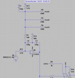
I see three coils are needed, and I need a feedback from three outputs, I did use a adder for this with resistors three times bigger
to low pass.
I did try the K facktor in LTspice, idea was one ferrite core with three parallel windings on it so I have to use just one coil, it did
simulate fine, If I have sim oke but real live not, I need for 5 level 4 coils, because I do use high frequenties these coils are small.
As you say, yes this circuit is much more stable, and more easy to control. But it needs 4 low pas coils for 5 level, and flying cap just one,
seen the low cost of the coils and maybe to use two separate windinds (or three) on one core will proberly work. Feedback is more
challenging because of the three or more outputs, I use resistor adder who works fine..
see pics.
I have play some with your attachment from Karsten, I had a mail contakt in past with this author because of feedback
circuit he did had on paper.
I see three coils are needed, and I need a feedback from three outputs, I did use a adder for this with resistors three times bigger
to low pass.
I did try the K facktor in LTspice, idea was one ferrite core with three parallel windings on it so I have to use just one coil, it did
simulate fine, If I have sim oke but real live not, I need for 5 level 4 coils, because I do use high frequenties these coils are small.
As you say, yes this circuit is much more stable, and more easy to control. But it needs 4 low pas coils for 5 level, and flying cap just one,
seen the low cost of the coils and maybe to use two separate windinds (or three) on one core will proberly work. Feedback is more
challenging because of the three or more outputs, I use resistor adder who works fine..
see pics.
Attachments
By the way, tv was broken and need repair, I did the job and look at the amp of the phillips tv because
this one did sound so sweet and quite open.
It was class D with a second order integrator no postfeedback.
chip was the TDA 7490L/.
https://eu.mouser.com/ProductDetail/STMicroelectronics/TDA7490L?qs=kndcJBrKlnSdzs4rAYhjjQ==
this one did sound so sweet and quite open.
It was class D with a second order integrator no postfeedback.
chip was the TDA 7490L/.
https://eu.mouser.com/ProductDetail/STMicroelectronics/TDA7490L?qs=kndcJBrKlnSdzs4rAYhjjQ==
That's a 3-phase common-mode coil, you need three separate ones ..I did try the K facktor in LTspice, idea was one ferrite core with three parallel windings on it...
Sure, but did you check how many MOSFETs, gate drivers and capacitors the 5-level flycap inverter needs ?But it needs 4 low pas coils for 5 level, and flying cap just one ..
Of course, not all class-D is PFFB.It was class D with a second order integrator no postfeedback.
Oke, all with all, the version with three bridges and coils I go try. I need indeed less electronic parts.
Because I am quite high in switching frequency I need not such big coils.
• Calculation of the Unity Gain Point. The amplifier is a "natural" sampling Amplifier. Sampling Theorem applies.
Specify nyquist distance : DNyquist := 3.25 unity gain FT/FL,
For the question about coil with K factor, yes it is a common mode coil, needed by the way for self oscillating three level.
because common mode voltage is higher, I do not now if this is here the case when in bridge,
Then mine question arise, how do I use the pré feedback, because I have three outputs who are fase shifted and then added. I have use a low pass for every output and added this to one signal with resistors. Using with a second orde integrator it did quite nice, (no postfeedback yet).
regards
You need separate chokes on separate cores, if I understand correctly. CM choke only gives a small leakage inductance between its windings (that are usually tightly coupled) and this small value is often not enough to suppress circulating currents between legs. These currents would worsen the efficiency and EMI performance of the amplifier.
The rest of what you've written (unity-gain point, Nyquist distance etc. ) I do not understand.
In EE, we generally take what we can have as we cannot always get all what we need.I need indeed less electronic parts.
Because I am quite high in switching frequency I need not such big coils.
The rest of what you've written (unity-gain point, Nyquist distance etc. ) I do not understand.
Hi
I have a lot of stuff here, so coils are not a problem, can even use air coils if inductance is low.
NYguist is the unity gain point, need to calculate that because of design of feedback. the low pass
is bound with this. I do now people here use other means to calculate the low pass -3 dB point.
when a 5 level do switch, the frequency is multiplied, so with 250 khz mosfet switching I get 1.25 Mhz.
There is a big bug in the new LTspice.
When used it for some time, it does not start simulating anymore, I can tick the button until I do
weight a ton, it just do nothing. and then crash. The scrolling is very bad, ald very slow.
Only restart do let it work again. I have a glitch also every 10 mseconds.
I had this al time already but did not mention it yet.
Unfortunately, what you mean is 5 phases / 5 legs switching and not 5-level switching .. It may be better to get off pseudo technical jargon or you'll remain on the simulator even after months have passed, not being able to graduate to anything real.when a 5 level do switch, the frequency is multiplied, so with 250 khz mosfet switching I get 1.25 Mhz.
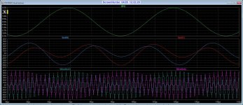
Here I have test the 5 level.
the phase shift do let multiply the frequentie on output, and suppress the triangle frequenties.
I have now other challences to do, and not much time to set up all.
I have almost ready the pcb cnc, when that is ready I go work on it. I had done a board for
testing, but that is a normal half self oscillating version to design feedback.
This moment I have make ready the greenhouse. I do sim sometimes to
relax and rust again. I do now I have to build some day things I have simulated.
Attachments
![DSCN5768[1].JPG](/community/data/attachments/1210/1210319-97b3f7019ac0945c4e2a480aabd22dee.jpg)
Hi
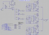
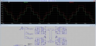
I have did some sims with the idea from the paper you did send me from Karsten Neilsen's paper on Parallel PSCPWM.
I did have a uge common mode voltages and see the pulse on the speaker with the differential mode low pass.
Calculating the coils is different because these are paralell, so double the inductance.
The only way to tackle this is using common mode low pass as this is normal used for BD systems.
on pic,s you see it. If I use only prepost feedback I get also common mode voltage problem with this low pass.
So did a design for the feedback using Pi, and that did remove the common mode voltage.
Multilevel flycap has not this problem also by the way.
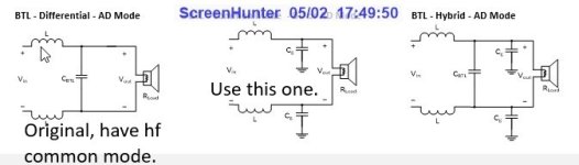
Oke as seen in plots, using a single ended version from nielse is a way, however generating 60 degree triangles
meet a problem, 90 degree is not a problem. Maybe I can use a johhson counter, set to 12 x output signal frequencion,
dividing signals can be very accurate.
regards
I have did some sims with the idea from the paper you did send me from Karsten Neilsen's paper on Parallel PSCPWM.
I did have a uge common mode voltages and see the pulse on the speaker with the differential mode low pass.
Calculating the coils is different because these are paralell, so double the inductance.
The only way to tackle this is using common mode low pass as this is normal used for BD systems.
on pic,s you see it. If I use only prepost feedback I get also common mode voltage problem with this low pass.
So did a design for the feedback using Pi, and that did remove the common mode voltage.
Multilevel flycap has not this problem also by the way.
Oke as seen in plots, using a single ended version from nielse is a way, however generating 60 degree triangles
meet a problem, 90 degree is not a problem. Maybe I can use a johhson counter, set to 12 x output signal frequencion,
dividing signals can be very accurate.
regards
Attachments
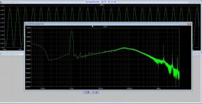
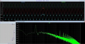
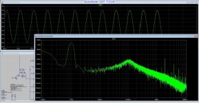
Here is the single ended 5 level, input 500 khz, output is 2 Mhz.
Becaause of it is single ended, I have not common mode trouble. Signal is so much cleaner.
Looks like btl for multilevel is not that good, except with some extra electronics and coils.
pic 1 btl, pic 2 single ended. you see noise level is quite higher in btl.
Becaause of it is single ended, I have not common mode trouble. Signal is so much cleaner.
Looks like btl for multilevel is not that good, except with some extra electronics and coils.
pic 1 btl, pic 2 single ended. you see noise level is quite higher in btl.
Attachments
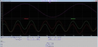
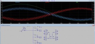
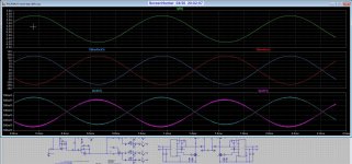
Common mode voltage, voltages between neutral, I am not shure I am confused with differential
voltages by the way..
On pic you see clearly this problem, with a common mode filter it is still present.
This problem is always present with BD pwm if there are differences in time and fase.
I did test again a postfeedback, fully differential input did removes the common mode completely.
See pic,s, where I use fast sim with perfect parts did lower the common mode significantly
with more precise delays. BD are prone to this, feedback can help.
When measuring the current over the speaker, then signal is very clean, but seeing pulses on
éach speaker terminal I do not like, these common mode voltages do give EMI through cables
possible do nothing with soundquality itselfs.
exciting stuff.
Attachments
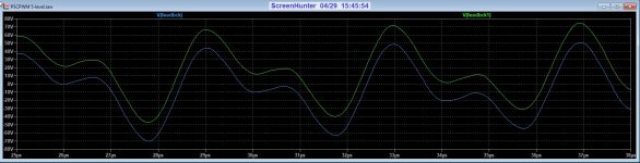
Welll, because I am not that calculate guru, I have seen that the common mode, or differential error was caused by
using a single input with btl BD stages. This problem is not present with a normal btl bridge.
I did need to set the triangle fases a other way for let this work, and that causes the differential error as a strange voltage
voltager on the output see the multilevel pulses there.
I did now use two feedback circuits and change the triangle signals such that the fases do cancel out the error.
THat means 0-180 degree for the left half bridge and 90-270 degree for the other half. When I use a single input an
common mode filter is needed.. and the fases are 0-90 for left half bridge and 180-270 for the other, audio is input
and do the 90 degree when it is inverted on one side, let it work fine.
I disagree, sinch each phase shares a part of the load current, the inductances can have lower saturation current when compared to the normal case.Calculating the coils is different because these are paralell, so double the inductance.
BTL does not use common mode filters but full separate filters for each leg. I think you're getting the fundamental things absolutely wrong, and like I said earlier, this is the consequence of too much simulation.Looks like btl for multilevel is not that good, except with some extra electronics and coils.
The cables are not supposed to have HF voltages nor are they supposed to carry HF currents, only audio. Once again, this appears to be a creation of your own methodologies, instead of using what is generally used.When measuring the current over the speaker, then signal is very clean, but seeing pulses on
éach speaker terminal I do not like, these common mode voltages do give EMI through cables
possible do nothing with soundquality itselfs.
If you do things your own way, I'm afraid noone on the forum would be able to help you, as you make methods and problems of your own.
Remember that neither multilevel nor BD means filterless. There is always a filter and there's must be the kind of filter that's recommended.
Hi Friend.
I have read the Niels paper again.
The common mode trouble I mention is there named as disadvance. I did now already for longer time that this happen in BD class d.
PSCPWM topology provides several advantages: · Only a single supply level is required, independent on the number of levels that need to be synthesized. · The breakdown voltage requirement to each of the transistors is halved. This is very important, since the paracitic components (e.g. capacitances) of the switching transistors depend heavily on the breakdown voltage.
The 'balanced drive' has the disadvantage of generating common-mode components over the load terminals.
Your mention about help, that is not really needed, I do just post some things and tips are always welcome.
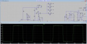
I know cases like current protection etc I have to implement. For flying cap tests, I can use a tracking circuit who do balance capacitor, works like a servo of a normal amp and do well, also I can use a resonance tank on output tned on the triangle carrier frequency and it balance also that way. the servo do send a voltage to the feedback opamp, it do compare the capacitor voltage with a voltage, in mine case a 40 volts. a resistor divider is used for lowering that voltage to prevent damage of opamp. But I do first try the more easy Niels way to see what it does.
Using the filter do work nicely. But need a extra coupled coil. I can do single end with 4 half bridges, but what bus pumping does then.
Pic has also square test and distortion as sim. If I am agree I build them one day.
I have read the Niels paper again.
The common mode trouble I mention is there named as disadvance. I did now already for longer time that this happen in BD class d.
PSCPWM topology provides several advantages: · Only a single supply level is required, independent on the number of levels that need to be synthesized. · The breakdown voltage requirement to each of the transistors is halved. This is very important, since the paracitic components (e.g. capacitances) of the switching transistors depend heavily on the breakdown voltage.
The 'balanced drive' has the disadvantage of generating common-mode components over the load terminals.
Your mention about help, that is not really needed, I do just post some things and tips are always welcome.
I know cases like current protection etc I have to implement. For flying cap tests, I can use a tracking circuit who do balance capacitor, works like a servo of a normal amp and do well, also I can use a resonance tank on output tned on the triangle carrier frequency and it balance also that way. the servo do send a voltage to the feedback opamp, it do compare the capacitor voltage with a voltage, in mine case a 40 volts. a resistor divider is used for lowering that voltage to prevent damage of opamp. But I do first try the more easy Niels way to see what it does.
Using the filter do work nicely. But need a extra coupled coil. I can do single end with 4 half bridges, but what bus pumping does then.
Pic has also square test and distortion as sim. If I am agree I build them one day.
Attachments
Newvirus.
Thanks for the help, I do post here regulair to let see the work.
O yes, I have done designs already, but never class D, I have a hybrid and a circlotron
half build, hybrid is build already years ago. I still do analog, but Class D is new
for me and simulating it can learn me much. I am very bad in calculations, always was
even on low school, some kind of blindness for figures.
For this reason I use axamples to get somewhere. The death ot mother and a friend
did also not make it worse what concerns the builds, but I get to it soon.
I stay post some thinking here, no reason to build things as most do, I like strange
tryouts.
- Home
- Amplifiers
- Power Supplies
- dead time question