I'll be happy to. What am I looking for on which device?
There is some hum leakage and other stuff and the close in spectrum around the fundamental is very interesting to compare. The Boonton works a lot like a synthesizer with active frequency correction. The KH relys on stable parts and circuitry. You can see humps on each side of the fundamental with the Boonton that aren't there with the KH. I'll upload pictures later.
Since you have a Boonton you may be interested in this: I have need for weighting filters for noise measurements. Boonton wants $300 ea. for them. (AP only wanted $110 for the A weighting filter.) I am laying out a PCB and will be buying the special parts for both the A-weighting filters and the CCIR-ARM filter. If you are interested let me know. I will be able to forward the expresspcb files and I can get extra resistors and caps for the project when I get them.
-Demian
here are the residuals of the Linear Oscillator -- 10kHz to 30kHz -- I used the averaging function to eliminate the environmental noise. there really is no second or third harmonic to speak of, but there is some distortion around 11, 12 and 13kHz which has to be dealt with. As I said earlier, I think that some of the R and C values have to be tweaked to get the phase crossing correct -- and this involves more than unsoldering a few devices.
An externally hosted image should be here but it was not working when we last tested it.
Are any residuals visible below 10K? I just looked at the KH at 10K. It measures .0018% w/ 80 KHz filter. But there are no close in residuals, even with the internal oscillator set to 1 KHz. The Boonton measures .0025% with no close in stuff.
Could they be in the spectrum analyzer you are using?
Demian
Could they be in the spectrum analyzer you are using?
Demian
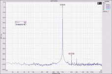
The spectrum analyzer I'm using is a 3577a -- here's a look at the Boonton Residuals -- 10kHz, 10V output -- scale is 20uV/div
An externally hosted image should be here but it was not working when we last tested it.
You need to be cautious of the input overload both for accuracy and frying the input mixer (probably not an issue with the 3577).
I have a passive input filter (a B&K 1607) that I use to atteunate the input. I can get a 70 dB notch that allows the analyzer to look into the mud better.
Here is my Boonton with a 70 dB notch in front of a Tek 7L5. The noise is lower at 10 Hz but I can't sweep a wide enough band, the slowest sweep is 10 seconds per div. and the amplitude isn't accurate if the sweep is rushed.
Attachments

And here is the KH4400 under the same settings.
Making a passive twin t filter isn't hard, the same as the equations for a wein bridge. And you will need to trim the components very carefully for the best notch.
It will be interesting to see how good the "super oscillator" is.
-Demian
Making a passive twin t filter isn't hard, the same as the equations for a wein bridge. And you will need to trim the components very carefully for the best notch.
It will be interesting to see how good the "super oscillator" is.
-Demian
Attachments

If you look at the components of the super-gain blocks in the oscillator, the RC combinations (390pF and 5k1) aren't correct for 10kHz -- i think that the peaking in the LT1230's is a bit higher so that there is a beat frequency at 1kHz which I can see in the spectragraph.
I already adjusted the capacitor values in the composite amplifier so that the fundamental is 10kHz.
Cyril Bateman used a passive 60dB notch filter in his capacitor testing article in EW.
I already adjusted the capacitor values in the composite amplifier so that the fundamental is 10kHz.
Cyril Bateman used a passive 60dB notch filter in his capacitor testing article in EW.
I did read the Bateman article with interest. I have two Radiometer CLT-1's and know them pretty well. He made a mistake in his assumptions on how the CLT-1 works. It actually has a high impedance at the 2-5 harmonics. I have used it to measure resistors, caps and pots and found a few interesting things.
If the circuit is generating those sidebands it must be pretty close to oscillation. You might be able to see that on a scope, but I'm not sure how. Possibly kill the oscillation and excite the circuit with a low amplitude squarewave and look for fuzz.
-Demian
If the circuit is generating those sidebands it must be pretty close to oscillation. You might be able to see that on a scope, but I'm not sure how. Possibly kill the oscillation and excite the circuit with a low amplitude squarewave and look for fuzz.
-Demian
OK -- Memorial Day afternoon -- I checked it out -- there is no distortion on the mains coming into the house, the neighbor's air conditioner blew a bearing and remains quiet -- here's the distortion residuals taken using the Tektronix DA4084 THD Analyzer -- the first snap is the Boonton 1120's oscillator, the second is the Super Oscillator. 2uV/div for the Boonton, 1uV/div for the SuperOsc. In fairness to the Boonton, the residuals taper down quite a bit after several minutes. I think that the frequency hopping challenges the amplification. There is also a 1.3kHz output which disappears after a few minutes for the Boonton.
Boonton 1120 Oscillator
Super Oscillator
Boonton 1120 Oscillator
An externally hosted image should be here but it was not working when we last tested it.
Super Oscillator
An externally hosted image should be here but it was not working when we last tested it.
ashok said:Can use a pasive or active filter at the output of the soundcard . I've tried this. You need to be very careful about stray hum pick up etc. It does promise very good results .
I'ved done this with a XCO, the Linear Technology LTC1063 filters, followed by a passive LPF -- the circuit was described by Charles Hansen in AudioXpress a few years ago -- the distortion is very low but you need the passive filter to remove the switcihng artifacts. I've also used a PIC and a Basic Stamp with decent results.
I don't know how happy a computer sound-card is in seeing a low-impedance load (600 ohm), but I know that there are folks on this board who can opine knowledgeably.

This morning I did a quick test with a two pole passive low pass filter into the Boonton. Essentially I confirmed that its internal distortion in the analyzer is its limit and a lower distortion external source won't measure lower.
I have explored tweaks on the Boonton (socketed IC's make this easy) and saw small improvements but nothing substantial.
This is all probably academic, since the distortions are unlikely to be audible at these -95dB plus levels. And the Boonton is easy and fast to use.
Demian
I have explored tweaks on the Boonton (socketed IC's make this easy) and saw small improvements but nothing substantial.
This is all probably academic, since the distortions are unlikely to be audible at these -95dB plus levels. And the Boonton is easy and fast to use.
Demian
PC signal generator
I have been using this approach now for over a year and a half. Attached is test signal after bandpass filter. In this case it is a state variable bandpass using the spare op amp (I use the OPA 4134 quad) as output buffer.
Input is a Sound Blaster Audigy II MX at 24 bits /96 KHz, and after checking different levels I believe the residual arctifacts are mostly in the acquisition path.
Next post is the raw soundcard output.
Rodolfo
ashok said:Can use a pasive or active filter at the output of the soundcard . I've tried this. You need to be very careful about stray hum pick up etc. It does promise very good results .
I have been using this approach now for over a year and a half. Attached is test signal after bandpass filter. In this case it is a state variable bandpass using the spare op amp (I use the OPA 4134 quad) as output buffer.
Input is a Sound Blaster Audigy II MX at 24 bits /96 KHz, and after checking different levels I believe the residual arctifacts are mostly in the acquisition path.
Next post is the raw soundcard output.
Rodolfo
Attachments


- Home
- General Interest
- Everything Else
- Low Distortion Signal Generator