Yes, I'd opt for the second drawing, this one:
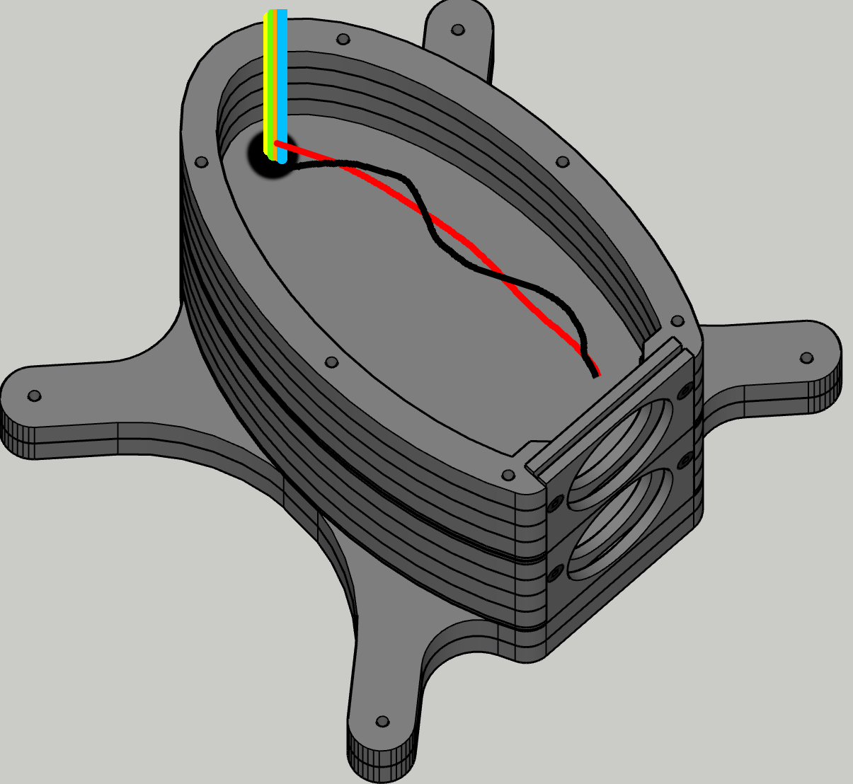
The hole needed for this is easy to seal with a rubbery glue and routing the wire is easy. That first option seems like a nightmare to route unless you do it as you build up the layers... i.m.h.o. that's not practical.
Personally I just drilled two small holes in each divider in my own arrays to be able to wire them, for practical reasons I put those holes much more forward, closer to back of the drivers so I could fill the chamber with damping material and route the wiring afterwards, next put a layer of wool felt on top to shield off the itchy fiberglass fill I used plus tucking away the wire run in the process...

I needed the headroom in wire length to be able to wire the baffle with drivers and mount the baffle to the enclosure afterwards..

In designing my arrays I've always kept one thing as a top priority: serviceability.
That's why I used certain materials and did not rely on wood screws etc. Everything is serviceable by bolting/unbolting without damaging any of the materials.
The hole needed for this is easy to seal with a rubbery glue and routing the wire is easy. That first option seems like a nightmare to route unless you do it as you build up the layers... i.m.h.o. that's not practical.
Personally I just drilled two small holes in each divider in my own arrays to be able to wire them, for practical reasons I put those holes much more forward, closer to back of the drivers so I could fill the chamber with damping material and route the wiring afterwards, next put a layer of wool felt on top to shield off the itchy fiberglass fill I used plus tucking away the wire run in the process...
I needed the headroom in wire length to be able to wire the baffle with drivers and mount the baffle to the enclosure afterwards..
In designing my arrays I've always kept one thing as a top priority: serviceability.
That's why I used certain materials and did not rely on wood screws etc. Everything is serviceable by bolting/unbolting without damaging any of the materials.
Last edited:
Yes, I'd opt for the second drawing, this one:
The hole needed for this is easy to seal with a rubbery glue and routing the wire is easy. That first option seems like a nightmare to route unless you do it as you build up the layers... i.m.h.o. that's not practical.
Personally I just drilled two small holes in each divider in my own arrays to be able to wire them, for practical reasons I put those holes much more forward, closer to back of the drivers so I could fill the chamber with damping material and route the wiring afterwards, next put a layer of wool felt on top to shield off the itchy fiberglass fill I used plus tucking away the wire run in the process...
View attachment 1095009
I needed the headroom in wire length to be able to wire the baffle with drivers and mount the baffle to the enclosure afterwards..
View attachment 1095012
In designing my arrays I've always kept one thing as a top priority: serviceability.
That's why I used certain materials and did not rely on wood screws etc. Everything is serviceable by bolting/unbolting without damaging any of the materials.
Hey by any chance do you have a master gallery of your build somewhere? Also do you recall what volume per driver you ended up with? I’m at 2L each, with a lot of stuffing right now.Yes, I'd opt for the second drawing, this one:
The hole needed for this is easy to seal with a rubbery glue and routing the wire is easy. That first option seems like a nightmare to route unless you do it as you build up the layers... i.m.h.o. that's not practical.
Personally I just drilled two small holes in each divider in my own arrays to be able to wire them, for practical reasons I put those holes much more forward, closer to back of the drivers so I could fill the chamber with damping material and route the wiring afterwards, next put a layer of wool felt on top to shield off the itchy fiberglass fill I used plus tucking away the wire run in the process...
View attachment 1095009
I needed the headroom in wire length to be able to wire the baffle with drivers and mount the baffle to the enclosure afterwards..
View attachment 1095012
In designing my arrays I've always kept one thing as a top priority: serviceability.
That's why I used certain materials and did not rely on wood screws etc. Everything is serviceable by bolting/unbolting without damaging any of the materials.
I’m trying to understand how you spaced the outer “vanity” baffle to the inner baffle- did the outer one just press against the driver edges? What thickness did you use for the chamfered outer baffle? I have it modeled for 1/4” but I’m not sure it will allow much rounding-over.
I ended up drawing another design, not using trans-lam. Looks like it’s going to be significantly cheaper to CNC and time-efficient to assemble.
The trans-lam was going to be too dependent on the materials being a very consistent thickness to maintain the layer spacing.
If I can find a few more hours next week I think I can get my order into the CNC guy by the end of the month.
Sorry, aside from a limited Pinterest collection I don't have a master gallery. It's all in that huge thread of mine though. I started with a write up of all the assembly work on my site: https://www.vandermill-audio.nl/, maybe some day I'll find the time to finish that  .
.
My volume per driver was about 2.1 liter. And I used plenty of damping material too. Wool felt on the walls and fluffy fiberglass in the middle. Making impedance tests to see it's effectiveness.
Outside baffle is 6 mm thickness, with an 8 mm fillet routed as driver cut-out. It used to rest on the top gasket of the TC9.
With the 10F I put a neoprene gasket on the backside of each cut-out that touches the driver frame. Where the bolts holding the baffle are, there's a thick neoprene seal and everywhere in between both baffles there's butyl rope to damp the vibrations of the baffle. Each bolt on the baffle has a neoprene washer.
Here's what the butyl rope looks like when disassembling:

You can also see the neoprene felt on the back of the baffle. (in this case you still see TC9, but without their gaskets).
The idea of that small roundover on the baffle is to have the seamless transition from the cone towards the enclosure shape:

This shape is helping to reduce the negative effects of diffraction at off-axis angles. Simulation shows it is working quite well.
The shape of the enclosure together with that baffle roundover was my secret sauce to get better off axis performance than standard rectangular boxes (as shown in a previous post). And the reason for me to use translam construction to be able to create it in my limited workshop. I did consider using a fiberglass hull construction but the shape really was essential for me.
Another detail: the back baffle rests on the enclosure using another neoprene seal (on top of a layer of mass loaded vinyl glued to the 10 mm aluminium inner baffle). The drivers are mounted to the inner baffle without any seal. They resemble a floating construction between enclosure and outer baffle.
Hope that helps...
.My volume per driver was about 2.1 liter. And I used plenty of damping material too. Wool felt on the walls and fluffy fiberglass in the middle. Making impedance tests to see it's effectiveness.
Outside baffle is 6 mm thickness, with an 8 mm fillet routed as driver cut-out. It used to rest on the top gasket of the TC9.
With the 10F I put a neoprene gasket on the backside of each cut-out that touches the driver frame. Where the bolts holding the baffle are, there's a thick neoprene seal and everywhere in between both baffles there's butyl rope to damp the vibrations of the baffle. Each bolt on the baffle has a neoprene washer.
Here's what the butyl rope looks like when disassembling:
You can also see the neoprene felt on the back of the baffle. (in this case you still see TC9, but without their gaskets).
The idea of that small roundover on the baffle is to have the seamless transition from the cone towards the enclosure shape:
This shape is helping to reduce the negative effects of diffraction at off-axis angles. Simulation shows it is working quite well.
The shape of the enclosure together with that baffle roundover was my secret sauce to get better off axis performance than standard rectangular boxes (as shown in a previous post). And the reason for me to use translam construction to be able to create it in my limited workshop. I did consider using a fiberglass hull construction but the shape really was essential for me.
Another detail: the back baffle rests on the enclosure using another neoprene seal (on top of a layer of mass loaded vinyl glued to the 10 mm aluminium inner baffle). The drivers are mounted to the inner baffle without any seal. They resemble a floating construction between enclosure and outer baffle.
Hope that helps...

Had to switch to a traditional cabinet construction, I just couldn't get the layer thickness to work with the materials I have at local stores.
Any ideas if I can get by with 1/2" for the wall thickness? My thinking is all the layers will give good bracing, and save me a decent amount of $ between the material and CNC time.
Still going to be doing the felt lining and rock wool stuffing. Mounting the drivers with putty/adhesive.

Any ideas if I can get by with 1/2" for the wall thickness? My thinking is all the layers will give good bracing, and save me a decent amount of $ between the material and CNC time.
Still going to be doing the felt lining and rock wool stuffing. Mounting the drivers with putty/adhesive.
Yes, I was thinking that a sandwich for the outer walls might be beneficial.Extending your 1/2" fiber wall to a sandwich will do. To example: Attach inside 1/4" rehab gypsum sheets by soft glue (carpet glue, butyl, viscoelastic etc)
Hope you succeed!
I'll look up the rehab gypsum sheet, ive never heard of that material. Thanks for the tip.
I was considering as simple as a layer of tempered hardboard with green glue between, or another 1/2" layer on the outside so that I can achieve more roundover of the front baffle.
I had an epiphany last night and now have to revisit my trans-lam design. I realized I could still arbitrarily place the layer dividers, that it didnt need to rely on the layer thickness. By trimming 1/4" in specific layers I can add the dividers wherever needed. Much happier to be using this approach, not having the rounded baffle/body shape was really a compromise that I was unhappy with. For now the dividers are going to be made from a sandwich of 1/8" tempered hardboard with green glue between.

Be sure you control the thickness of whatever material you use for the trans-lam construction. I opted for birch ply over MDF due to my assumption the first would have less vertical movement. I still needed to do this:


But that has worked for the long haul.... it would be my recipe for a next time, if I ever would do it again, to have flexible layers at certain spots from the start.
And a nice coat of epoxy/glasfiber mat to top it off. I haven't had any problems since....
But that has worked for the long haul.... it would be my recipe for a next time, if I ever would do it again, to have flexible layers at certain spots from the start.
And a nice coat of epoxy/glasfiber mat to top it off. I haven't had any problems since....
I remember reading in your thread about the crack saga. Must have been heartbreaking.Be sure you control the thickness of whatever material you use for the trans-lam construction. I opted for birch ply over MDF due to my assumption the first would have less vertical movement. I still needed to do this:
View attachment 1107052
View attachment 1107053
View attachment 1107054
But that has worked for the long haul.... it would be my recipe for a next time, if I ever would do it again, to have flexible layers at certain spots from the start.
And a nice coat of epoxy/glasfiber mat to top it off. I haven't had any problems since....
I am working out how to handle this in my build.
Several approaches im considering: maybe avoid using glue entirely and use clamping force from nuts/washers on the threaded rods, and use a 1/16" rubber layer every 5 rows to allow expansion/contraction, thats at least 1.5" of rubber material spread out in the stack.
Or a softer/flexible adhesive like green glue and minimal clamping force- including plastic/delrin nuts that would fail if pressure got too high?
The environment they'll live in is humidity controlled, so thats a plus.
My take away from your thread was that you had glued the layers and left the threaded rods tightened in place, with the threaded rods not allowing for expansion, leading to the failure? Was that the case after everything was settled?
I like the idea of wrapping them epoxy/fiber, it would solve for aesthetic issues since its quite a look unto itself. I've never worked with that medium though so it would need a few trial runs to ensure success. I'd want to see how you terminated the wrapping when it reached the baffles, that seems like the trickiest part at first look.
Thanks again for all the help. Super excited to be back on the trans-lam approach.
My take away from your thread was that you had glued the layers and left the threaded rods tightened in place, with the threaded rods not allowing for expansion, leading to the failure? Was that the case after everything was settled?
That's not quite right... the rods were somewhat free to move, I had rubber washers on the top and bottom, around every 2 layers there was a flexible rubbery glue in contact with the rods. The crack was contraction, the wood shrunk in size overnight due to a humidity change! It cracked on a few "ply" layers, not my glued layers. It happened so fast, the wood and glue didn't have time to adjust. It was with a big loud "bang". I didn't even realize what that bang was until it opened up further over night.
That flexible glue around the rods wasn't a great idea. But being that large a stack, it would probably have cracked anyway, I've seen other, smaller stacks crack without the rods. I think it's a good idea to have flexible layers of a proper thickness to solve this problem. Making smaller stacks, less overall risk.
I like the idea of wrapping them epoxy/fiber, it would solve for aesthetic issues since its quite a look unto itself. I've never worked with that medium though so it would need a few trial runs to ensure success. I'd want to see how you terminated the wrapping when it reached the baffles, that seems like the trickiest part at first look.
I've first soaked the enclosure in epoxy, and after that, while it was still somewhat wet, I wrapped the fiberglass matt around and soaked that, working up the layers wet in wet, look at a few boat building tutorials, I sure did. After it was completely soaked I wrapped it real tight in household plastic foil to keep it's shape. After curing I could cut off the excess matt and it stayed nice and tight following the curves. The outside was shaped due to the tight winded plastic foil... a bit rough and with folds from the plastic as an imprint...
I sanded it to get a rough structure for the next step.
Around that first layer, I used epoxy with microballoons (glass bubbles) to thicken the mix (much like creating a filler substance) and added a couple of layers of that till I got the finish I wanted. I used rollers meant for boat building, the regular foam rollers would implode when using them with epoxy (it heats up as it cures).
I won't tell how one of them fell out of my hands when exchanging the left/right arrays and I had to redo a cracked epoxy bottom end
.This was 2 layers, I think I did 3 in total. 2 Years ago, when I placed the filters in my arrays, I re-did 2 outer layers with microballoons.
Over the years the wood had left enough imprint to see the cuts etc. as can be seen in this post.
I used boat paint on top of the epoxy, to make it UV proof. A 2 part coat, at least 2 layers. (I used this both times)
Quite a bit of work, I almost forgot, one more note to add: I sealed the inside with epoxy too, at least 2 coats with white color added so I could see the coverage was good enough. The only picture I have of that is when I used it as a wine rack just before the Christmas season:
I finished them shortly after... the outside texture looking like this:
Depending on thickness of the epoxy/microballoon mix and the roller used. Even the speed of the application did have some influence.
I was after this look, as it would hide small imperfections. The paint is silk gloss. I did my subwoofers using the same paint treatment:
Brings back a lot of memories
Last edited:
I covered the complete build here: https://www.vandermill-audio.nl/?page_id=295
Enough info to build your own version, including the logo (lol).
Enough info to build your own version, including the logo (lol).
I had to go back to the box format. Just couldn't make the economics of the layers work, it would be more than double for materials and CNC time.
Here is a cross section of the final. First pic is the add-on panels for bigger roundover. Second and third show the box layers.
Trying to decide if I need more bracing, maybe triangle cuts along the corners?
Considering things like a layer of ram-board (thick solid flat cardboard like material) with damping glue lining the inside with felt lining then rockwool.
Also could add another 1/2" thick panel on each side to make the whole front wider, and have more roundover. Would attach it with damping glue. For now I'm waiting on an updated quote from my CNC folks.
Attachments


Last edited:
Had to table the process for a bit, work got busy- but now I'm itching to get back into it.
Anyone have thoughts about using thick cardboard tubes behind the baffle? I've found 3.1" OD x 12" tubes (0.1" thickness), which would yield 1.3L volume. The driver spacing is 3.3" CTC. There would be just enough space for a 1/8" ply spacer between them.
I'd line them with felt for the first 6" then progressively stuff them ending with some 4" of dense rockwool.
My understanding about cylinder shaped enclosures is the rear surface is the most problematic, but with enough stuffing wouldn't it be just a "black hole" with little to no return?
It could also be made aperiodic with a thick fabric instead of a solid material at the end, that would solve that resonance issue? Any thoughts? I've used this driver in the XRK style "dagger" 3-sided pyramid and it sounded much better than any box i've tried it in ever since. That triangle pyramid shape isn't feasible with the line array spacing.
Attachments

Ok, long dormant but I have cut some wood! Hoping to have the inner portion of the towers done today or tommorow and I'll post some pics.
Meanwhile I'm looking at whether I should try to include some form of "constrained layer damping" between the inside and outside panels (between teal and red panels). I've read a bit but its confusing as to whether elastic silicone adhesive will be sufficient, or whether I'll need to seek out "GreenGlue" Other places have suggested a layer of plasticine/plastilina clay, which is a non-drying modeling clay. I found some at michaels and its similar to what we used to call "fun-tack".

Meanwhile I'm looking at whether I should try to include some form of "constrained layer damping" between the inside and outside panels (between teal and red panels). I've read a bit but its confusing as to whether elastic silicone adhesive will be sufficient, or whether I'll need to seek out "GreenGlue" Other places have suggested a layer of plasticine/plastilina clay, which is a non-drying modeling clay. I found some at michaels and its similar to what we used to call "fun-tack".
Wood has been cut. Inner layer and inner baffles are cut. Checked fit with one baffle, only 3 spots where I’ll need to fix the cutout by 1/8”. Honestly much better than I was expecting.
Next steps are chamfering the second baffle cutouts. Then routing slots for the shelves on the inside walls.
Next steps are chamfering the second baffle cutouts. Then routing slots for the shelves on the inside walls.
Attachments


Joke all you want but its $12/sheet vs $85+ for not great plywood here, and my woodworking skill level is not there yet for spending decent $$ on 3-4 sheets. The OSB is plenty robust when using 2 layers, and is quite dead acoustically. I can always layer a bit of MDF/Hardboard to make a nice smooth exterior. Personally I like to sand it very smooth, stain black, finish with a few layers of clear then satin poly. It has a nice subtle texture, feels great. Hard to scratch, and easy to touch up.
- Home
- Loudspeakers
- Full Range
- TC9 active line array questions