Thanks. I’m definitely expecting to do a mk2 at some point down the road.
I need to pick your brain about where you’ve landed with shading and low-pass for the array. I have a few ideas from the near-field and cbt papers.
Either shading low-pass based on the ctc (single driver plays above ~4100hz).
Near field paper suggests shading by power, with the drivers farthest from center being maybe -6db.
I’d love to hear what you landed on so I can start in a good place. I also need to determine what the power requirements for individual drivers are- I have built a nice module with pam8406 that does fantastic up to 1W into 8ohm. If I need more I’ll have to step up to something like a tpa3116.
There is an easy-to-use line array model discussed in this thread that supports both shading and curvature. I never bothered to add the crossover or some other features that I was considering, but it works fine for full range drivers.
Also, that line array project you mentioned in post #6 is getting updated. Here is my $50 48-channel DSP:

Also, that line array project you mentioned in post #6 is getting updated. Here is my $50 48-channel DSP:
That board looks great. I found it on eBay and may have to order one for myself. Is there any documentation?
My current solution is 3x 1u boxes of legacy dsp. 1 per line and 1 for input. Certainly would be nice to reduce that to a small board and include it in the amplifier chassis.
I read through the linked thread with the array software, didn’t see any consensus on best approach- is that still the case?
My current solution is 3x 1u boxes of legacy dsp. 1 per line and 1 for input. Certainly would be nice to reduce that to a small board and include it in the amplifier chassis.
I read through the linked thread with the array software, didn’t see any consensus on best approach- is that still the case?
I don't know if there is a best approach for full height arrays using full range drivers, but that modeler might help you visualize some alternatives.
My interest has been for multiway arrays to avoid those comb filtering issues. The design I am working on now will use 1/2" headphone drivers for the tweeter array, along with a midrange array using low cost 3" drivers. I prefer off-loading the low frequencies to a separate cabinet, as it makes all those vibration issues easier to deal with. I'll document the design as it comes together--right now I'm focusing on the control software for the DSP.
My interest has been for multiway arrays to avoid those comb filtering issues. The design I am working on now will use 1/2" headphone drivers for the tweeter array, along with a midrange array using low cost 3" drivers. I prefer off-loading the low frequencies to a separate cabinet, as it makes all those vibration issues easier to deal with. I'll document the design as it comes together--right now I'm focusing on the control software for the DSP.
I'm sure a single tweeter could help address some of the comb filtering issues, but other issues arise. The tweeter will act as a point source with 1/r^2 attenuation with distance, whereas the line array falls off at 1/r. Modeling that behavior is complicated, because you need a good 3D model to visualize the overall response. The modeler that I hacked together for that "understanding the line array" thread sums the response along the vertical axis, with the assumption that the response along the x axis is uniform. But with a point source in the middle that assumption is no longer valid. For many years I've wanted to work with 3D ray tracing tools from game developers to develop better models, but I've never gotten around to it.
I'm sure a lot of designers have tried the single tweeter line array, but I haven't seen any reports on this approach.
I'm sure a lot of designers have tried the single tweeter line array, but I haven't seen any reports on this approach.
In nc535's thread he played with the concept of using a single tweeter in a full range array. All I remember is that it wasn't easy ") .
.
(you might want to revisit that thread for ideas though)
My array is still divided into 5 group of 5 drivers, though I've spread one group around the central 5 drivers. The thread I mentioned has a lot of experimental ideas worked out in Vituixcad, like: https://www.diyaudio.com/community/...-corner-placement.337956/page-35#post-6265943 (idea from @ra7 ) and it highlights that the center driver gets into trouble to reach the output levels. Which is why I stayed with 5 groups of 5 drivers, to keep the output potential high, much higher than that of a single driver. Also the reason why I used frequency shading, and not regular shading. The low notes and high notes are the most difficult to get right, so I wanted all of the drivers to help in the bottom end, and I compromised on the top end for output levels.
The single tweeter has to be something very efficient with a specific pattern to match the array, it will probably work best at a single distance and listening height. There are commercial examples though, like Adyton...
But also plenty of DIY projects, like: https://no.pinterest.com/sand3196/loudspeakers-design-by-willy-sand/ (this guy does post here on this forum at times)
.(you might want to revisit that thread for ideas though)
My array is still divided into 5 group of 5 drivers, though I've spread one group around the central 5 drivers. The thread I mentioned has a lot of experimental ideas worked out in Vituixcad, like: https://www.diyaudio.com/community/...-corner-placement.337956/page-35#post-6265943 (idea from @ra7 ) and it highlights that the center driver gets into trouble to reach the output levels. Which is why I stayed with 5 groups of 5 drivers, to keep the output potential high, much higher than that of a single driver. Also the reason why I used frequency shading, and not regular shading. The low notes and high notes are the most difficult to get right, so I wanted all of the drivers to help in the bottom end, and I compromised on the top end for output levels.
The single tweeter has to be something very efficient with a specific pattern to match the array, it will probably work best at a single distance and listening height. There are commercial examples though, like Adyton...
But also plenty of DIY projects, like: https://no.pinterest.com/sand3196/loudspeakers-design-by-willy-sand/ (this guy does post here on this forum at times
)
Last edited:
I need to pick your brain about where you’ve landed with shading and low-pass for the array.
https://www.diyaudio.com/community/...range-line-array.242171/page-392#post-7305543
Not shading by power, but by frequency. Running the Scan Speak 10F's from 200 Hz and up, the TC9 could go lower more easily. Not a hard crossover, I use a low shelf to reduce power below ~200 Hz. It helps to still have them work with the subwoofers to get a better total low end. Yet, they don't have to work hard for that to happen. (circumventing room trouble and instead using the room)
Thanks. ~60mm radius curve, once the steps are sanded and smoothed.
I'm picking everything up tomorrow from the sign shop. About $600 and 3mo to have it done.
I need to make a schedule for all the various assembly tasks. With my last project I got excited and glued it up before I should have, and made assembling internals super difficult.
I'm picking everything up tomorrow from the sign shop. About $600 and 3mo to have it done.
I need to make a schedule for all the various assembly tasks. With my last project I got excited and glued it up before I should have, and made assembling internals super difficult.
I'd say, if this functions as well as a proper sanded curve, I'd be inclined to leave it as is?
I think it looks quite cool as is, especially in a soft or matte finish. It kinda looks "technical".
If it isn't too much work, maybe it could easily be tested in simulation? That is, if you like the look yourself.
@fluid ? Would it be as easy as I think it would be? I'd say if the steps are small enough, and it does look that way, there's probably not much if any difference. Saving you time and making it "interesting" to look at.
It kind of reminds me of the grooves in the baffle of the Gryphon speakers:

Another example:

I think it looks quite cool as is, especially in a soft or matte finish. It kinda looks "technical"
.If it isn't too much work, maybe it could easily be tested in simulation? That is, if you like the look yourself.
@fluid ? Would it be as easy as I think it would be? I'd say if the steps are small enough, and it does look that way, there's probably not much if any difference. Saving you time and making it "interesting" to look at
.It kind of reminds me of the grooves in the baffle of the Gryphon speakers:
Another example:
Last edited:
Very small steps won't make much difference in real life, it is tricky to model as the mesh resolution needs to be high and then because everything is completely reflective small steps will introduce diffraction like noise making it hard to see anything useful.If it isn't too much work, maybe it could easily be tested in simulation? That is, if you like the look yourself.
For the best diffraction performance sand it or fill it so it is smooth.
If you like the look then you are balancing aesthetic performance vs acoustic performance
my plan was to have a nice smooth curve- most important was having consistency over the whole thing. I worry the keeping the small edges will be revealing of any imperfections or dents.
Filler might be easier than sanding- I've had luck previously using a spreader made to match the desired shape. The filler will need sanding, but removing filler will be more forgiving-I can always add more.
Filler might be easier than sanding- I've had luck previously using a spreader made to match the desired shape. The filler will need sanding, but removing filler will be more forgiving-I can always add more.
Last edited:
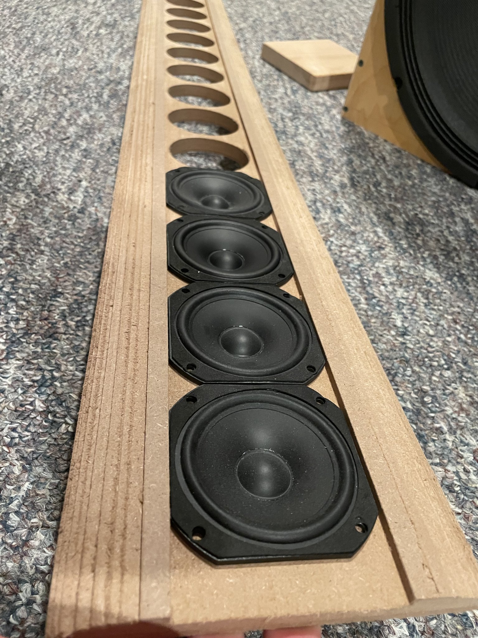
Filled+sanded the first baffle with bondo and it’s very nice and smooth. Damn that stuff is noxious though- I can only manage working with it entirely outside.
I brought the second one in to test fit drivers. Perfect. Just great work from the CNC shop. They’ll be perfectly flush with the baffle once they have some seal putty behind them.
Lots more to do- but having the pieces here means it’s going to be real soon enough!
I brought the second one in to test fit drivers. Perfect. Just great work from the CNC shop. They’ll be perfectly flush with the baffle once they have some seal putty behind them.
Lots more to do- but having the pieces here means it’s going to be real soon enough!
Attachments


Don't want to be a drag, but if I see this:
All I can think of is putting a nice chamfer on those holes.... see: http://www.troelsgravesen.dk/chamfer.htm
Even though my (inner) baffle was only 10 mm in thickness, I still made sure the drivers could breathe...


P.S. if that's still planned but not yet executed, I didn't say a thing.
All I can think of is putting a nice chamfer on those holes.... see: http://www.troelsgravesen.dk/chamfer.htm
Even though my (inner) baffle was only 10 mm in thickness, I still made sure the drivers could breathe...
P.S. if that's still planned but not yet executed, I didn't say a thing
.@wesayso Thanks- I noted that you’d done that in your og build thread. Still jealous of that gorgeous aluminum. I plan to do some chamfering- the dividers between each driver means I can do a small chamfer above and below, a full one on the sides.
Meanwhile I filled the front curve and have sealed and primed.
I think I’m going to leave it here until it’s glued with the sides. Guessing it will need filler where the baffle meets sides. Then I’ll prime the sides…..I always forget there’s so much prep that goes into painting and finishing.

Meanwhile I filled the front curve and have sealed and primed.
I think I’m going to leave it here until it’s glued with the sides. Guessing it will need filler where the baffle meets sides. Then I’ll prime the sides…..I always forget there’s so much prep that goes into painting and finishing.
- Home
- Loudspeakers
- Full Range
- TC9 active line array questions