Tony's latest traffo DIY build

Member
Joined 2003
Hi Mr Tony.

Some basic level questions, please if you can cooperate with me.

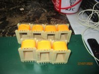
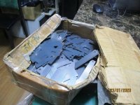
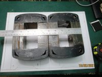
Before assembling the set, each individual lamination plate E and I has some insulating cover ... (some dielectric varnish for example). ?

the thin oxides at the surface served as insulation albeit no a perfect one, just use them...

For power transformers, there are many differences between using grain oriented and non-grain oriented lamination.

goss irons can run at higher flux densities with lower losses than say a noss...
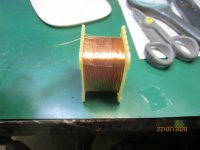
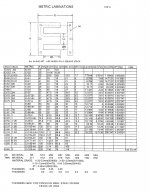
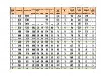
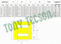
i use the M18 grades 0.35 for power traffos and M6/Z11 0.35mm thick laminations for output transformers..

In transformers in general, it is mandatory that the each layer wire must occupy the entire width of the bobbin. ?

yes as much as possible, except in cases of high voltages, where creepage distance is observed....


Where do you buy and what are the specifications of the lamination you use? . Is the same for PT and OPT transformers ?

I have 0.5 millimeter non-oriented grain lamination available .... but I have my doubts regarding this, final operating temperature, noise, etc.

Can you help me to model a power transformer for TSEII 2A3.

It is now or never, I want to assemble the power transformer for a Tubelab SEII amp, with two 2A3, two 5842 and one 5AR4 valves.....accompanied by two OPT Trascendar 3K/8 ohms.
Several here have used Hammond 370 HX for Power Transformer....

Thanks in advance Mr Tony.

0.5mm thick will also do for power transformers, you need to run them lower flux densities though...

for a 2A3, filament power is 2.5vac x 2 amps or 10 watts total..
two 5842 is 6.3vac x 0.3 amps or 4 watts
5ar4 is 5vac x 2amps or 10 watts,

so for filaments alone you need 24 watts
for plate psu supply 300 vdc at 100ma or 30 watts..

so that is 54 watts in all

the primary of your power traffo needs 54/0.6 or 90 volt amperes

this is minimum, nothing stops you from using bigger..
 
Member
Joined 2003
rm18 traffo........for a tube amp......
 

Attachments

  • IMG_1929.jpg
    IMG_1929.jpg
    879.5 KB · Views: 410
  • IMG_1930.jpg
    IMG_1930.jpg
    872.1 KB · Views: 402
  • IMG_1933.jpg
    IMG_1933.jpg
    913.6 KB · Views: 399
  • IMG_1936.jpg
    IMG_1936.jpg
    883.6 KB · Views: 408
  • IMG_1938.jpg
    IMG_1938.jpg
    978.8 KB · Views: 401
  • IMG_1939.jpg
    IMG_1939.jpg
    995.7 KB · Views: 254
  • IMG_1942.jpg
    IMG_1942.jpg
    989.2 KB · Views: 246
  • IMG_1941.jpg
    IMG_1941.jpg
    983.1 KB · Views: 261
Member
Joined 2003
rm18 is a grade of steel, lower than an m6/z11 but superrior to M58/H50...also it is 0.35mm thick, very good to use for pwoer trafos...and even output trafo...
 
Member
Joined 2003
these are tables i made to assist you in designing trafos....ampacity can be anywhere from 700 circular mils per ampere to 300 cma, i start design using the 500 cma column..
 

Attachments

  • wire table.jpg
    wire table.jpg
    406.7 KB · Views: 281
  • traffocoretable.jpg
    traffocoretable.jpg
    111.9 KB · Views: 242
Banned
Joined 2019
Banned
Joined 2019
If there's really a rectifier, I'd short it's diodes by applying wire bridges appropriately.
Best regards!

Thanks but my question is more general : I don't want to modifiy the module, so what is the risk to apply a 30-0-30 VDC to a 20-0-20 AVC on that module with an integrated rectifier ?
Just want to know if it is going to work ? )
 
Last edited:
Member
Joined 2003
your amp shows too many filter caps, so then i doubt that smps is what you need..

looks like toroid traffo is all you need.....

HTB1YazPjgfH8KJjy1zcq6ATzpXaZ.jpg
 
Last edited:
Banned
Joined 2019
your amp shows too many filter caps, so then i doubt that smps is what you need..

I know that amigo ) But my question is not what I need but what I risk : In other words : Will the rectifier allow DC current to pass without causing damage to the module? I guess the diode bridge will set the polarity automatically from power inputs ?
 
Member
Joined 2003
I know that amigo ) But my question is not what I need but what I risk : In other words : Will the rectifier allow DC current to pass without causing damage to the module? I guess the diode bridge will set the polarity automatically from power inputs ?

sorry for very late reply, but i think you will need a soft starting circuit for this module...
 
Member
Joined 2003
6kg. C-Cores for output traffos, a pair each for SE and PP, high voltage....up to 2.5kv....mandrels are being fabricated...
 

Attachments

  • IMG_2081.jpg
    IMG_2081.jpg
    984.6 KB · Views: 295
  • IMG_2082.jpg
    IMG_2082.jpg
    762 KB · Views: 287
  • IMG_2088.jpg
    IMG_2088.jpg
    986.8 KB · Views: 275
  • IMG_2085.jpg
    IMG_2085.jpg
    976.7 KB · Views: 264
  • IMG_2089.jpg
    IMG_2089.jpg
    964 KB · Views: 220
Banned
Joined 2019
sorry for very late reply, but i think you will need a soft starting circuit for this module...

I figured it out ) You can use both SMPS or Linear PSU with it. If you go for the SMPS you need a dual rail one with the correct current. You will have a Diode loss but it works the same :)
 
Top