

The Amplifier of 100 Transistors (output devices)
In my previous post I presented an idea spawned from a very bad place, primarily boredom and probably too much alcohol. Plane trips from Australia do that...
The Amplifier of 100 Transistors was the result.
Between that posting and this a few things have happened. I finished the design - adding extra decoupling and 100 Ohm base resistors to all 104 output devices. I did this because I sincerely thought I was building more of an RF oscillator than amplifier.
And I built it.
And I got it working.
This is the beast from the back before I loaded the "output devices":
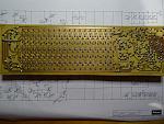
Note the ludicrous number of emitter and base resistors! Half way through I concluded that I was bonkers, and wasting several days hand building a complete folly.
Then again, even with the thing running, it is still a folly!
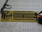
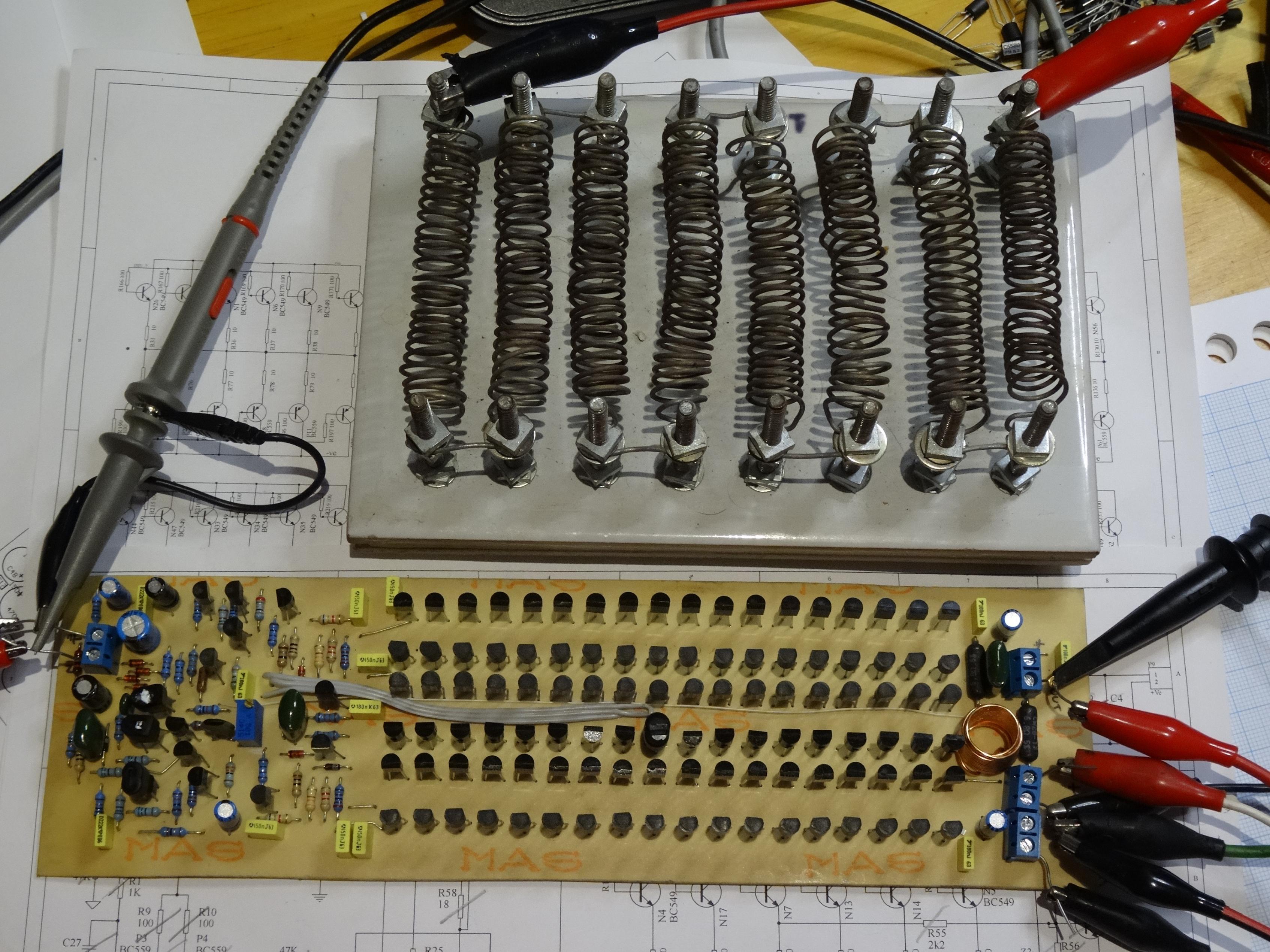
With the output devices loaded. Note that t set it to work I started with a single "output pair" and got it all set up, then added an extra 17 "output pairs" to make a whole row. That is where I saw oscillation.... Increasing the negative rail filtering resistor from 10 Ohms to 47 Ohms settled that down, even into 4 Ohm loads.
And running into a dummy load.
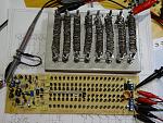
Flat out this amplifier will deliver about 10-15 Watts, so the dummy load is barely aware it is being used!
I have not run it hard for long periods, not have I measured distortion and suchlike. I will do that next, now that I have a decent distortion measurement system.
So there you go, the Amplifier of 100 Transistors!
And as I said 30+ years ago, if you can't do it with a BC549, it isn't worth doing!
A few notes:
- The devices I used came from reels, and obviously common batches. I am not a massive advocate of matching HFE's etc - but I did note that the PNP devices had HFE's of 340 +/- 5 on my random multimeter tester, and the NPN devices had a HFE of 440+/- 10 on the same meter.
not that I really care about the HFE, the tests were really to ensure that I did not load one dead transistor amongst 100 others and create an easter hunt for myself!
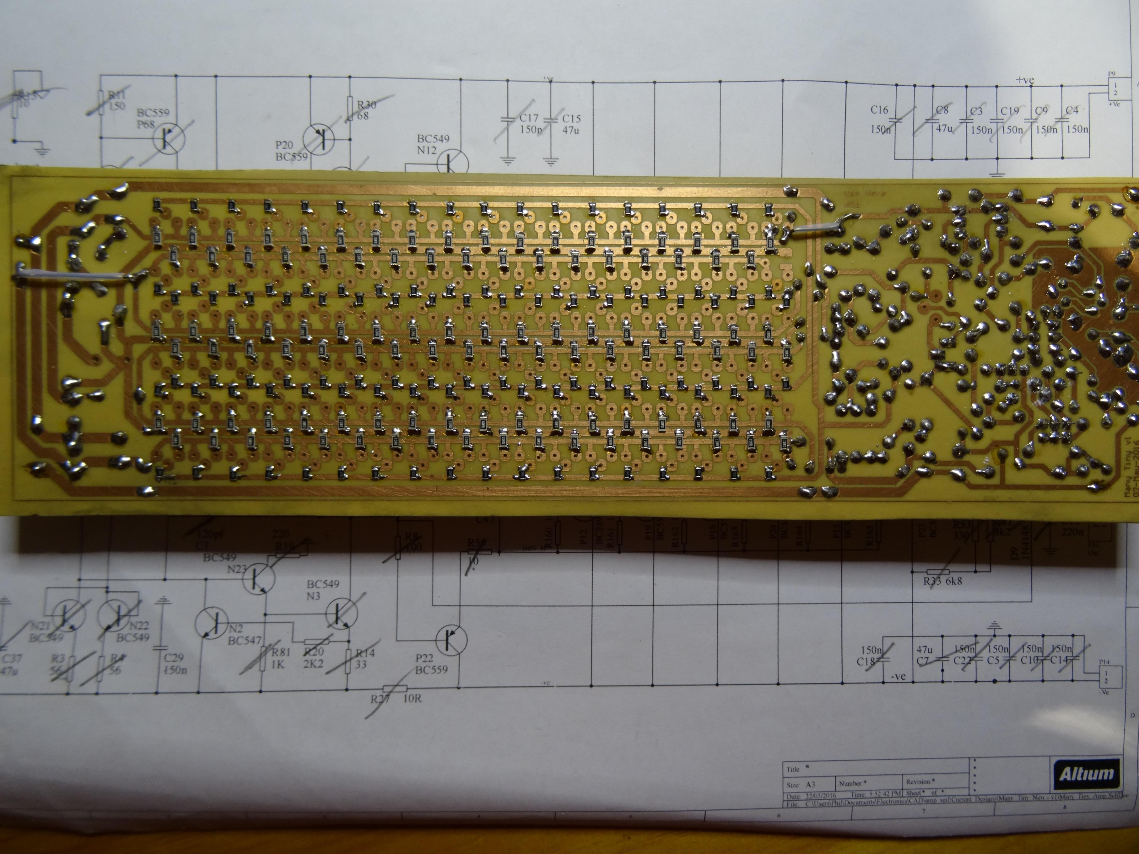
I will post the final schematic and layout just for completeness. Do note however that your mileage is likely to vary considerably on stability of the amplifier, I rather think that the thing is just stable what with the rubbish layout and output devices with gain more like a Darlington's!
If you try this let me know how you go!
The Amplifier of 100 Transistors was the result.
Between that posting and this a few things have happened. I finished the design - adding extra decoupling and 100 Ohm base resistors to all 104 output devices. I did this because I sincerely thought I was building more of an RF oscillator than amplifier.
And I built it.
And I got it working.
This is the beast from the back before I loaded the "output devices":
Note the ludicrous number of emitter and base resistors! Half way through I concluded that I was bonkers, and wasting several days hand building a complete folly.
Then again, even with the thing running, it is still a folly!
With the output devices loaded. Note that t set it to work I started with a single "output pair" and got it all set up, then added an extra 17 "output pairs" to make a whole row. That is where I saw oscillation.... Increasing the negative rail filtering resistor from 10 Ohms to 47 Ohms settled that down, even into 4 Ohm loads.

And running into a dummy load.
Flat out this amplifier will deliver about 10-15 Watts, so the dummy load is barely aware it is being used!
I have not run it hard for long periods, not have I measured distortion and suchlike. I will do that next, now that I have a decent distortion measurement system.
So there you go, the Amplifier of 100 Transistors!
And as I said 30+ years ago, if you can't do it with a BC549, it isn't worth doing!
A few notes:
- The devices I used came from reels, and obviously common batches. I am not a massive advocate of matching HFE's etc - but I did note that the PNP devices had HFE's of 340 +/- 5 on my random multimeter tester, and the NPN devices had a HFE of 440+/- 10 on the same meter.
not that I really care about the HFE, the tests were really to ensure that I did not load one dead transistor amongst 100 others and create an easter hunt for myself!
I will post the final schematic and layout just for completeness.
Do note however that your mileage is likely to vary considerably on stability of the amplifier, I rather think that the thing is just stable what with the rubbish layout and output devices with gain more like a Darlington's!If you try this let me know how you go!
Total Comments 1
Comments
-
 This is a awesome project, I love itPosted 21st June 2016 at 10:32 AM by MR Overclock


