

Now For Something Completely Different - In a Neat Little Box!
After a few months of playing with loudspeaker drivers and software fixes to code that I wished I had never written in the first place, the lure of the BJT loomed large again...
There I was, sitting at my desk, and pondering where these dark feelings were coming from and how to scratch that evil itch, and my eyes came to rest upon that most ludicrous of things - the amplifier of 100 transistors.
About a year ago, or so it seems to me sitting here, I built this homage to the BC549, or as the engineer in me says, "Laughably stupid thing, which probably shouldn't work. Who would be dumb enough to try and find out?".
It needed a case. It needed a power supply. It deserved each of the above that would allow it to work, and ideally take an equally "left field" approach. it should never have been built, but it had. It should have been put in the back of a very dark, locked cupboard, but it had not.
The idea then became:
- The "Amplifier of 100 Transistors" is, as alluded to above, made entirely from BC549/BC559 devices.
- This has "one or two" implications. Not the least of which is that they are 30 volt devices, so whilst I could probably get away with +/-15V unregulated rails, it would be such bad form that the voice of reason in the back of my head screamed "You need a regulated power supply".
- Second implication - the "heatsink" kind of relies on good convection.
- The execution of the packaging really did need to highlight the concept of using small signal transistors as output devices in all of its misguided glory.
- I wanted the transistors to be visible, indeed I wanted them to be "in your face".
About 20 years ago I restored a LEAK TL/12 valve amplifier. Which I subsequently gave away (!). The nagging voice in the back of my head prompted me to take inspiration from that amplifier in this implementation - putting the output devices right op top, where you can see them.
So the following came about...
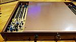
The gold hammer tone colour being drawn from the LEAK chassis. Devices on "top" and a few features in the design that are less obvious:
- The lights on the front are grain of wheat light bulb fixtures that I found in the bottom of a parts draw. None of these modern rubbish LED things...
- Hidden inside the chassis are TWO complete mono-block amplifiers using two transformers, two power supplies and two completely independent speaker protectors. The only connection being the power switch.
Regulators I hear you say? Yhea. The thing runs of +/-16V regulated rails, which at clipping into no load means the "output devices" will be seeing 30volts peak.
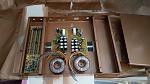
Inside there is the following:
- two 50VA transformers
- two powers supplies with 8800uF per rail each, and linear regulators. I used MJL21193/4 devices because I couldn't work out how to do this with BC549's in any same manner...
- Two speaker protectors - using BC549/559 of course!
I made the case in the shed, as for some stupid reason you can't buy cases like this from he shop.
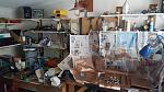
It was raining, so I decided to paint the thing inside...

and, yes I have wracked my brain looking for a plausible excuse as to how the input sockets came to be 10mm offset from the centre line of the rear panel. The best excuse I can come up with is that I either fell asleep at the drill, or stopped too long at the beer fridge, which is about 15 feet behind me...
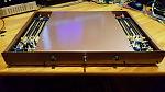
Built up it looks like this:

and yes, there is clearance between the transformer bolts and the lid.... just.
The thing will deliver between 10 and 15 Watts into 8R, and pretty much double that into 4R. With the regulated supply, there will be no rail droop
As measured last year, the distortion is improbably low, this is a very clean amplifier.
I feel like I ought to wax lyrical about how wonderful small signal transistors sound, how "fast" they are and how much detail each and every one of them adds to each musical note. I should proclaim that the amplifier being open to the air delivers an airiness to the sound that is absent from all other amplifiers ever built and that this is unique.
But I wont.
This amplifier will definitely be paired with the Richard Allan CG10 bass drivers and some high efficiency tweeters. Those RA CG10 drivers measure something in the region of 93-95dB/W at one metre. While I was testing them I almost fell off my chair with the noise they made at normal test settings. I am not sure I have found the right tweeter yet - and that is purely because of the half dozen or so pairs of peerless, scan speak, vifa and Morel tweeters I dug out of the speaker cupboard - NONE of them were as efficient as those bass drivers.... Sounds like a match made in heaven for a 15 Watt amplifier!
I am looking forward to properly testing this amplifier, and creating a suitably retro / ludicrous / possessed set of speakers to go with it!
If you are wondering why I would go to all this effort, the only explanation I can give is that I was really, really bored. I might have been temporarily insane and there is even a chance that I was both drunk and possessed at the time. I make no claim to logic or reason in this!
There I was, sitting at my desk, and pondering where these dark feelings were coming from and how to scratch that evil itch, and my eyes came to rest upon that most ludicrous of things - the amplifier of 100 transistors.
About a year ago, or so it seems to me sitting here, I built this homage to the BC549, or as the engineer in me says, "Laughably stupid thing, which probably shouldn't work. Who would be dumb enough to try and find out?".
It needed a case. It needed a power supply. It deserved each of the above that would allow it to work, and ideally take an equally "left field" approach. it should never have been built, but it had. It should have been put in the back of a very dark, locked cupboard, but it had not.
The idea then became:
- The "Amplifier of 100 Transistors" is, as alluded to above, made entirely from BC549/BC559 devices.
- This has "one or two" implications. Not the least of which is that they are 30 volt devices, so whilst I could probably get away with +/-15V unregulated rails, it would be such bad form that the voice of reason in the back of my head screamed "You need a regulated power supply".
- Second implication - the "heatsink" kind of relies on good convection.
- The execution of the packaging really did need to highlight the concept of using small signal transistors as output devices in all of its misguided glory.
- I wanted the transistors to be visible, indeed I wanted them to be "in your face".
About 20 years ago I restored a LEAK TL/12 valve amplifier. Which I subsequently gave away (!). The nagging voice in the back of my head prompted me to take inspiration from that amplifier in this implementation - putting the output devices right op top, where you can see them.
So the following came about...

The gold hammer tone colour being drawn from the LEAK chassis. Devices on "top" and a few features in the design that are less obvious:
- The lights on the front are grain of wheat light bulb fixtures that I found in the bottom of a parts draw. None of these modern rubbish LED things...
- Hidden inside the chassis are TWO complete mono-block amplifiers using two transformers, two power supplies and two completely independent speaker protectors. The only connection being the power switch.
Regulators I hear you say? Yhea. The thing runs of +/-16V regulated rails, which at clipping into no load means the "output devices" will be seeing 30volts peak.
Inside there is the following:
- two 50VA transformers
- two powers supplies with 8800uF per rail each, and linear regulators. I used MJL21193/4 devices because I couldn't work out how to do this with BC549's in any same manner...
- Two speaker protectors - using BC549/559 of course!
I made the case in the shed, as for some stupid reason you can't buy cases like this from he shop.

It was raining, so I decided to paint the thing inside...
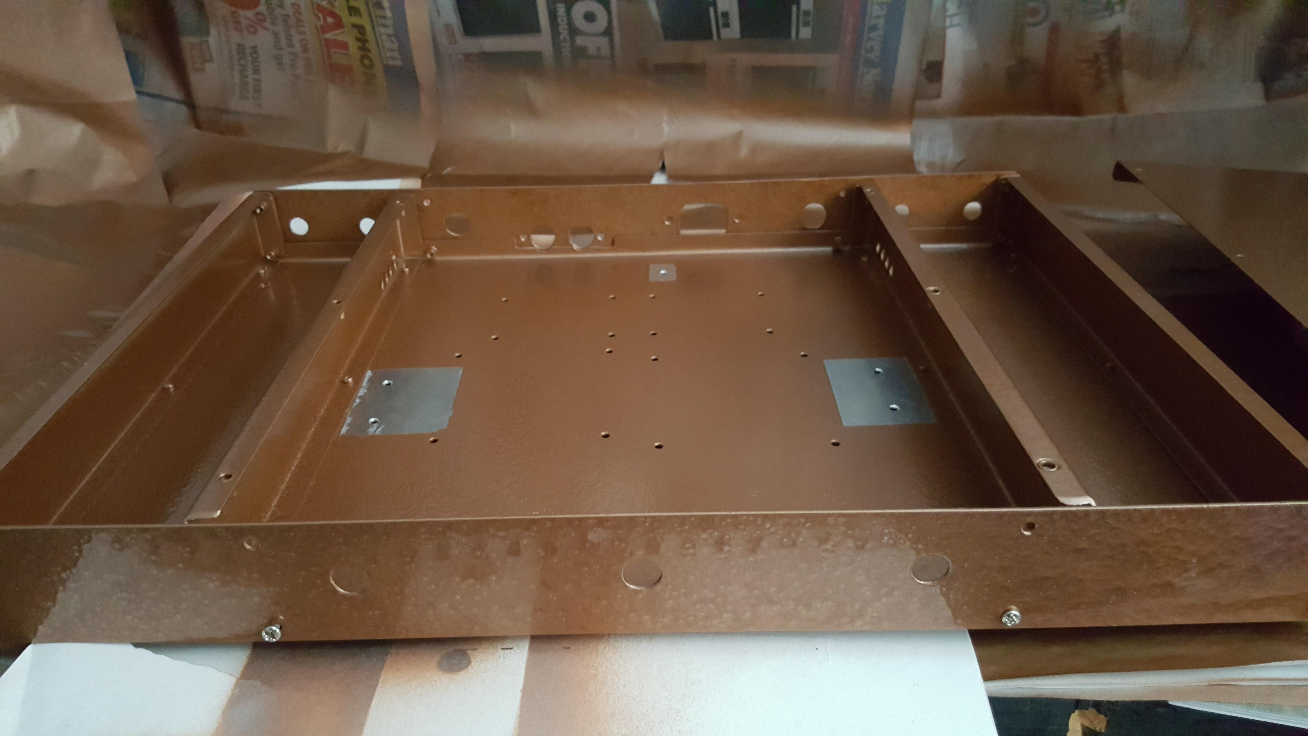
and, yes I have wracked my brain looking for a plausible excuse as to how the input sockets came to be 10mm offset from the centre line of the rear panel. The best excuse I can come up with is that I either fell asleep at the drill, or stopped too long at the beer fridge, which is about 15 feet behind me...

Built up it looks like this:
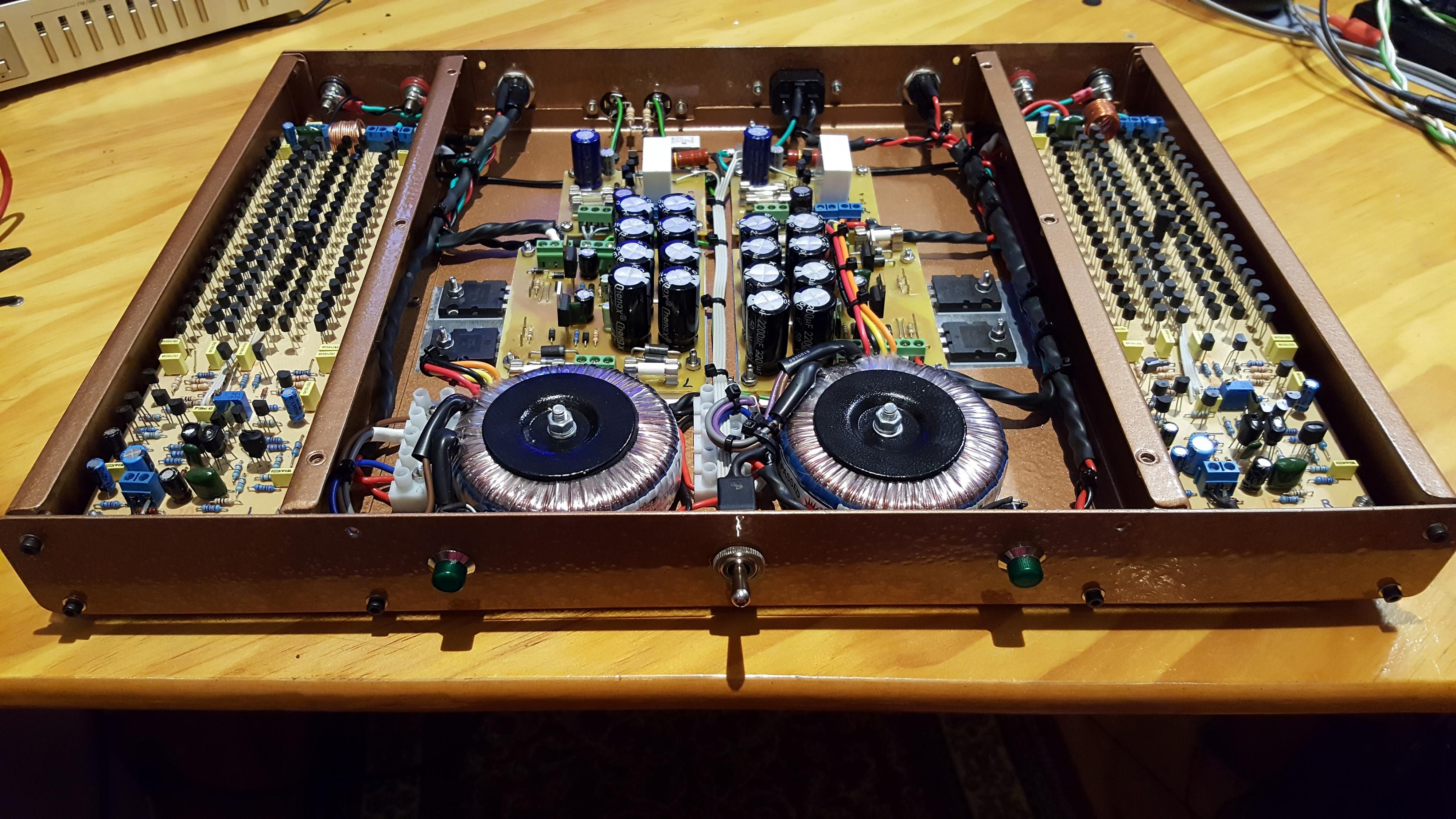
and yes, there is clearance between the transformer bolts and the lid.... just.

The thing will deliver between 10 and 15 Watts into 8R, and pretty much double that into 4R. With the regulated supply, there will be no rail droop
As measured last year, the distortion is improbably low, this is a very clean amplifier.
I feel like I ought to wax lyrical about how wonderful small signal transistors sound, how "fast" they are and how much detail each and every one of them adds to each musical note. I should proclaim that the amplifier being open to the air delivers an airiness to the sound that is absent from all other amplifiers ever built and that this is unique.
But I wont.
This amplifier will definitely be paired with the Richard Allan CG10 bass drivers and some high efficiency tweeters. Those RA CG10 drivers measure something in the region of 93-95dB/W at one metre. While I was testing them I almost fell off my chair with the noise they made at normal test settings. I am not sure I have found the right tweeter yet - and that is purely because of the half dozen or so pairs of peerless, scan speak, vifa and Morel tweeters I dug out of the speaker cupboard - NONE of them were as efficient as those bass drivers.... Sounds like a match made in heaven for a 15 Watt amplifier!
I am looking forward to properly testing this amplifier, and creating a suitably retro / ludicrous / possessed set of speakers to go with it!
If you are wondering why I would go to all this effort, the only explanation I can give is that I was really, really bored. I might have been temporarily insane and there is even a chance that I was both drunk and possessed at the time. I make no claim to logic or reason in this!
Total Comments 4
Comments
-
 Cool!Posted 22nd April 2017 at 09:36 PM by mrkramer

-
 That is amazing. Soldering 200 TO-92 transistors though. I think I would blow a fuse before hitting 50.Posted 24th April 2017 at 12:41 AM by rjm
-
Ha and you need to add to that the 200 off 0805 smd emitter resistors and 200 off 0805 base resistors!
Yet another reason this is bonkersPosted 24th April 2017 at 12:45 AM by googlyone
-
This is so fffffabulous ! I love the look of the whole thing and the execution is brilliant too.. jealous jealous !!Posted 24th April 2017 at 02:30 PM by kasey197

