Posted 25th February 2015 at 01:24 PM byrjm (RJM Audio Blog)
Updated 26th February 2015 at 12:41 AM byrjm
The HD600s.
Ok, so why dont you like the K702s?
I didnt say I didnt like them. Just that I think the HD600s are better.
Its pretty simple really:
The K702s have a strident, hard upper-midrange "bump" that I find disagreeable. Yes, it makes tracks sound more live, but its also fatiguing and a bit clinical, and - as many others before have noted - makes the sound overall somewhat thin. In direct comparison the HD600s seem full the point of boominess, but I'm willing to accept that midbass plumpness for the Sennheiser's warmer, luxurious midrange. In imaging, the K702s trend to a wide, distant, airy soundstage while the HD600s run towards a closed in, intimate presentation. In that sense the K702 are more like listening to speakers, and I can certainly see people being attracted to that.
These are both top-shelf headphones at the top of their game, I don't mean to imply that the AKGs are bad. The two...
Posted 22nd February 2015 at 02:24 AM byrjm (RJM Audio Blog)
Updated 28th February 2015 at 07:17 AM byrjm
I've added an additional RC filter stage (R3, C4 in the schematic below) before the Zener diode, substantially reducing the amount or ripple on the transistor base by cleaning up the voltage applied to the Zener reference. (The original Z-reg is described here.)
Circuit shows C2 with a value of 300 uF. Typically much larger values are used. I kept the filter capacitance to a minimum here to show circuit working with a reasonably high ripple (1 V p-p) on the input. The rectifier diodes used here are of no particular consequence, I just wanted the simulation to generate a realistic sawtooth for the input.
***
OK, this doesn't do as much as I originally thought. The improvement is mostly below 100 Hz, whereas the ripple is mostly in the 100Hz-1kHz band. There's perhaps 3 dB less output ripple, but that's about it. You can verify this yourself in LTSpice, just cut the wire between C4 and the junction or R1-R3 and rerun the sim.
Posted 16th February 2015 at 12:50 AM byabraxalito Updated 6th September 2015 at 05:28 AM byabraxalito(Red Wine it isn't, just the same designer)
Here's something very misleading in the 6moons preview of Vinni Rossi's (of Red Wine Audio fame) latest supercapacitor powered kit. They have 18 * 350F supercaps in the box and they say '...the total rating becomes a whopping 6300F'. However each capacitor is only 2.7V so presumably to get any audio signal at all out, they need to operate these caps in series. Caps in series don't multiply, they divide so the total capacitance drops by a factor of 18. Hence only 19.4F. Not a small difference from 6300F or did I miss something?
I think I may have missed something - they aren't using all the supercaps all the time, rather there are 9 discharging and 9 charging. So the total capacitance in the audio circuit at any time is 350/9 = 39F. Still an impressive amount of capacitance but the problem is that the ESRs add too....
Posted 14th February 2015 at 12:47 PM byrjm (RJM Audio Blog)
Updated 12th April 2015 at 02:59 AM byrjm
Technical Specifications:
Signal Input : 2x XLR female , balance
2x RCA, unbalanced
Maximum input level : +21 dBu, impedance 10kΩ
Input impedance : XLR: 10kΩ, RCA: 68kΩ
Input Sensitivity : +6 dBu
Main amplifier gain : +8 dB
Main amplifier gain adjustment range : -4 / +2 / +8 / +14 / +20 dB
Frequency response : 0-55kHz (-0.5dB)
Damping Factor :> 400 @ 50Ω
Dynamic range :> 128dB (A -weighted )
THD + N (1kHz 1W @ 100Ω): <0.00035%
THD + N (1kHz 0.5W @ 32Ω): <0.0007%
Crosstalk :-110db (1kHz)
Each channel has a BB OPA134PA - socketed - for voltage amplification and an eight transistor discrete buffer with 2 ea. 2SA1837. 2SC4793, C546B, C556B. Dual mono layout - more or less ... the circuit board itself is shared and not completely symmetric. There's a pair of NE5532s at back for balanced-unbalanced...
Posted 13th February 2015 at 05:16 PM bywlowes Updated 4th May 2016 at 12:44 AM bywlowes(Marconi 5U4GB NOS pair of rectifiers-awesome!)
Disclaimer that this entry is just a scrap book of my personal journey with a build. No fresh engineering here, so those seeking engineering insights can save the read.
That said, my new music server is now fully burned in, and for me its a delight. It is a collage of ideas developed by diyaudio members and by Lukas Fikus, aka Lampizator. Thanks to all who contributed. I hope these notes pass on some ideas for others.
Basic Approach
My approach is heavily influenced by Lukas of Lampizator fame. I have enjoyed his tube output amp design in my previous DAC, and several cd players. He got me interested in the TDA1541a, and I have had many years of happlily tweaking it for best sound. This server has a clone of his level 6 DAC with tube rectifiers, dual mono supply and film caps in CLCLC configuration.
Also, my digital evolution came via CICS CMP which taught me to appreciate a minimalist PC processor with network attached storage...
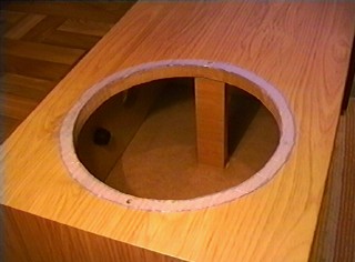
I bought these speakers in 2000. I was unhappy with the way they reproduce low frequencies. I decided to add a subwoofer. I used the fact that the lower part of the housing of the speaker is empty and isolated from the upper part in which the speakers operate. I cut a hole in the side of the bottom part and installed a 25 cm driver.
It is Vestra PW-250-2154 woofer.It has a 19 cm coated-paper membrane, foam external suspension, extruded metal sheet basket, ventilated 4.5 cm coil, the diameter of the magnet is 12 cm, 80 W, 4 ohms, the self-resonance (Fs) at 27 Hz.
I damped the interior of this newly created enclosure space with bitumen mat and felt glued to the walls and filled it with fleece. I cut out the rear wall from the top part of the enclosure. Inserted a reinforcing crossbars into the lower and upper housing. The upper part of the housing is entirely filled with a damping material (with fleece filled pillow, which...
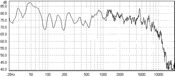
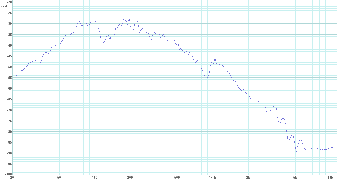
All measurements done with Panasonic WM-61A microphone with Eric Wallin preamplifier and E-MU0202. Single driver frequency response without any crossover. The microphone is located at a distance of 1 meter from the driver on its main axis.
Vifa 3075 dome tweeter:
Vifa TC 3520 woofer:
Vestra PW-250-2154 woofer with it's crossover, microphone located 10 cm from the driver:
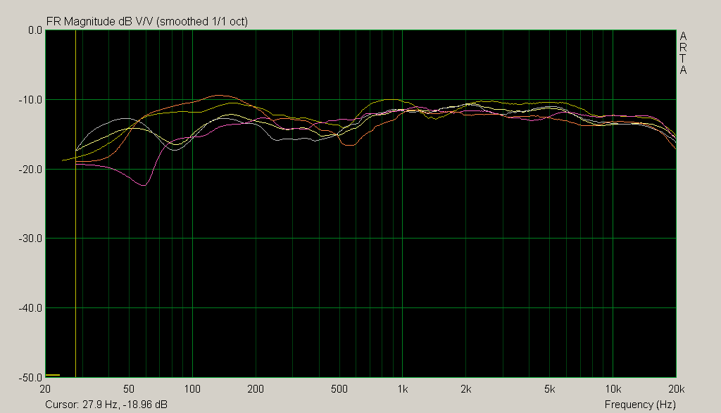
The complete speaker after modification.
Measurements done at my usual listening spot, 2.5 m from the speaker, microphone positioned 50 cm closer, farther, higher and lower around the spot. Obtained frequency response curves are strongly smoothed, because changing the position of the microphone produces a large change in the jags of the curve, and I wanted to show invariant features of the speaker frequency response:
It is pretty flat, and the bass is very nice now....
Posted 7th February 2015 at 07:47 AM byrjm (RJM Audio Blog)
Updated 14th February 2015 at 10:13 AM byrjm
I recently obtained a pair of AKG K702 headphones to complement my long-standing reference Sennheiser HD 600s. I figured since I'm building headphone amplifiers it would be a good idea to have a reference grade low impedance model as well as the high impedance HD 600s to use for evaluation.
At the same volume position I quickly discovered the HD 600s play slightly louder than the K702s. The datasheet values predict the K702s should be about 3 dB louder, so it seems the sensitivity is off by as much as 6 dB.
In numbers,
K702: 62 ohms, 105 SPL/V ... 93 dB/mW from datasheet, 87~89 dB/mW (99~101 SPL/V) in practice.
HD 600: 300 ohms, 97 dB/mW ... 102 SPL/V.
The K702 requires as much as ten times more power to drive than the HD 600s. The voltage sensitivity is about 3 dB lower than...
Posted 31st January 2015 at 01:28 PM byrjm (RJM Audio Blog)
Updated 18th March 2015 at 01:52 AM byrjm(add photo of finished amp)
A couple of years ago I built a standard op amp + diamond buffer headphone amplifier, called the Sapphire.
My original circuit (Sapphire 1.x) was the simple four transistor four resistor diamond buffer of the LH0002. Later small resistors (Sapphire 2.0) were added to the emitters of the driver transistors to boost the output bias current.
In this next go-round (Sapphire 3.0), I've replaced the emitter resistors with current sources. This provides a significant improvement in PSRR, over 20 dB in simulation. The output pair has been reinforced in a Sziklai configuration for lower distortion, and the primary output transistors five-way paralleled for improved thermal stability. The output impedance is 1~2 ohms, limited primarily by the output resistor.
It simulates to <-100 dB harmonics for 0 dB (1 V rms) output into 60 ohms. The total circuit standing current is less than 50 mA per channel.