Go Back   Home > Forums > Blogs

Old

DIY ES9018 DAC + LM4780 AMP Details part 3

Posted 6th January 2015 at 12:29 PM by Maciej Czerwinski

POWER SUPPLIES
Power supply for the amplifier is made out of two HP 0957-2093 printer power supplies (32V, 2.5A output), removed from their original plastic boxes and fastened together with metal bolts, nuts and plastic isolating spacers. This way they form one unit, producing +32V and -32V needed for the LM4780. Additionally there are two banks of six 1500uF/35V low ESR noise bypass capacitors in parallel at the output of the power supply. They greatly reduce switching noise, which has a peak at a frequency of around 30 kHz. There are also four 2200uF/35V caps soldered directly to the amp boards.
I have chosen the switching mode power supply instead of a classic 50Hz transformer because. SMPS is lighter, smaller, voltage regulated, requires less decoupling capacitance, does not produce any audible hum or spurious magnetic field around it . It’s main disadvantage is production of HF noise, but, as I am going to show later, it is not a big issue when the output is properly...
Attached Thumbnails
Click image for larger version

Name:	softstart.jpg
Views:	1327
Size:	73.7 KB
ID:	1484   Click image for larger version

Name:	zas_ogolny_sch.png
Views:	536
Size:	10.1 KB
ID:	1485   Click image for larger version

Name:	zas_hp1.jpg
Views:	229
Size:	71.5 KB
ID:	1486   Click image for larger version

Name:	zas_hp2.jpg
Views:	168
Size:	59.3 KB
ID:	1487   Click image for larger version

Name:	zas_wzm1.jpg
Views:	329
Size:	59.0 KB
ID:	1488  

Click image for larger version

Name:	caly_str_lewa.jpg
Views:	590
Size:	118.9 KB
ID:	1489   Click image for larger version

Name:	sps_THX203.png
Views:	2649
Size:	16.3 KB
ID:	1490   Click image for larger version

Name:	zas_dac3.jpg
Views:	217
Size:	63.2 KB
ID:	1491   Click image for larger version

Name:	zas_dac4.jpg
Views:	232
Size:	63.8 KB
ID:	1492   Click image for larger version

Name:	zas_dac2.jpg
Views:	211
Size:	103.4 KB
ID:	1493  

diyAudio Member
Posted in Uncategorized
Views 1811 Comments 0 Maciej Czerwinski is offline
Old

DIY ES9018 DAC + LM4780 AMP Details part 4

Posted 6th January 2015 at 12:28 PM by Maciej Czerwinski

The post-regulation schematics:
Click image for larger version

Name:	dac_zas_sch.jpg
Views:	2893
Size:	125.2 KB
ID:	1494
ThreeTHX203 SMPS boards soldered to the main power supply board. There are also additional 230V input filter, output bypass caps and gyrator’s TIP122 visible:
Click image for larger version

Name:	dac_zas_3zi.jpg
Views:	1505
Size:	97.7 KB
ID:	1495

The other side of the main board – LT1763 regulators, 5V main power daughterboard with heatsinks:
Click image for larger version

Name:	zas_dac_all.jpg
Views:	573
Size:	65.3 KB
ID:	1496

Details of the 5V main power daughterboard. The top heatsink is for the LM1763, the two on the bottom are for TIP122 (gyrator) and LM7805 (5V for volume controller):
Click image for larger version

Name:	zas_dac_5V.jpg
Views:	502
Size:	51.6 KB
ID:	1497

ADM7150 3.3V regulators on separate board with Rubycon ZL 4700uF/6.3V low ESR bypass caps (board bottom):
Click image for larger version

Name:	zas_dac12.jpg
Views:	411
Size:	62.1 KB
ID:	1498

(board top):
Click image for larger version

Name:	zas_dac14.jpg
Views:	220
Size:	62.0 KB
ID:	1499

This photos show the how dac power supply is mounted inside the housing:
Click image for larger version

Name:	caly_str_prawa.jpg
Views:	449
Size:	93.9 KB
ID:	1500Click image for larger version

Name:	caly_prawa_z_gory.jpg
Views:	288
Size:	88.5 KB
ID:	1501
diyAudio Member
Posted in Uncategorized
Views 2076 Comments 0 Maciej Czerwinski is offline
Old

DIY ES9018 DAC + LM4780 AMP Details part 5

Posted 6th January 2015 at 12:28 PM by Maciej Czerwinski
Updated 6th January 2015 at 12:36 PM by Maciej Czerwinski

Graphs showing the dac power supply output noise. You can see the SMPS switching frequency noise peaks at 26kHz and 32kHz. Their frequency rise a little when more current is drawn from the supply. It seems that the dac playing 1kHz is an example of the hardest load to regulate for the supply:
Click image for larger version

Name:	smps_vs_noise_floor3.png
Views:	319
Size:	15.6 KB
ID:	1502
Click image for larger version

Name:	smps_vs_noise_1khz.png
Views:	209
Size:	16.8 KB
ID:	1503
Click image for larger version

Name:	smps_vs_noise_wn.png
Views:	157
Size:	17.3 KB
ID:	1504
Click image for larger version

Name:	smps_vs_noise_fuga.png
Views:	144
Size:	16.9 KB
ID:	1505


VOLUME CONTROLLER:
It’s a PIC16F84 running a program written by me. It reads rotary encoder and accordingly writes values, via I2C, to the ES9018 attenuation registers. It writes single value to all 8 registers every tick of the encoder. After 10 seconds of no encoder activity, it stores the value to the internal EEPROM of the microcontroller.
The controller board has its own 3.3V regulator, the display board has 1.8V regulator for LEDs
The display module is a separate I2C dumb reader. It catches the attenuation values transmitted...
Attached Thumbnails
Click image for larger version

Name:	ES9018_I2C_PIC16LF84_Volume_simple.png
Views:	957
Size:	12.9 KB
ID:	1506   Click image for larger version

Name:	vol_disp.png
Views:	497
Size:	69.8 KB
ID:	1507   Click image for larger version

Name:	reg_glosn3.jpg
Views:	210
Size:	52.3 KB
ID:	1508   Click image for larger version

Name:	reg_glosn1.jpg
Views:	213
Size:	81.2 KB
ID:	1509   Click image for larger version

Name:	reg_glosn2.jpg
Views:	127
Size:	51.2 KB
ID:	1510  

Click image for larger version

Name:	reg_glosn4.jpg
Views:	137
Size:	161.2 KB
ID:	1511  
diyAudio Member
Posted in Uncategorized
Views 937 Comments 0 Maciej Czerwinski is offline
Old

DIY ES9018 DAC + LM4780 AMP Details part 6

Posted 6th January 2015 at 12:28 PM by Maciej Czerwinski
Updated 6th January 2015 at 06:18 PM by Maciej Czerwinski

HOUSING:
Typical steel box consists of four pieces bolted together. Dimensions: 440 x 100 x 255 mm (W x H x D). Notice the "Acqua di Gio" volume knob

Click image for larger version

Name:	caly_przod_obud.jpg
Views:	214
Size:	22.0 KB
ID:	1519
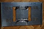
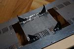
Bottom piece. I made two holes to let air flow through power amp heatsinks. There are corresponding holes in the top piece. The black plastic pieces are heatsink mountings:
Click image for larger version

Name:	dno.jpg
Views:	257
Size:	57.8 KB
ID:	1512
Click image for larger version

Name:	dno2.jpg
Views:	347
Size:	45.1 KB
ID:	1518
Top cover and side walls form one piece. I glued same aluminum mesh into heatsink airflow holes in order to protect the inside of the housing.
Click image for larger version

Name:	pokr_spod.jpg
Views:	289
Size:	40.6 KB
ID:	1513

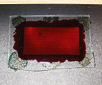
Detailed view of front piece inner side. Display protecting glass cut out of old picture frame and painted with red transparent paint. Total DIY:
Click image for larger version

Name:	szybka_wysw.jpg
Views:	336
Size:	117.7 KB
ID:	1514

MEASUREMENTS:
Output of the power amplifier loaded with 3.9Ohm resistor, connected to Left line input of the E-MU 0202 with two 10uF unipolar electrolytic caps. E-MU...
Attached Thumbnails
Click image for larger version

Name:	pomiar_wzm.jpg
Views:	312
Size:	49.9 KB
ID:	1515   Click image for larger version

Name:	thd_n_gotowy_dac_amp.png
Views:	265
Size:	7.9 KB
ID:	1516   Click image for larger version

Name:	imd.png
Views:	162
Size:	9.7 KB
ID:	1517   Click image for larger version

Name:	pasmo.png
Views:	153
Size:	3.8 KB
ID:	1520  
diyAudio Member
Posted in Uncategorized
Views 949 Comments 0 Maciej Czerwinski is offline
Old

New year, new DAC

Posted 31st December 2014 at 08:36 AM by abraxalito
Updated 3rd August 2015 at 12:50 AM by abraxalito

Here's the 'Ozone desktop pagoda' DAC for 2015.

A single TDA1387 feeds a 3 inductor quasi-elliptic filter followed by AD8017s as buffer-amps. The large ferrite cores in the base do the bal-SE conversion. The power supply is 4 * AA NiMH cells which should in theory last for a whole day's music.

The design is really a 'MkII' version of the Ozone portable where the AD815 buffers have been replaced to allow a more compact construction and lower power draw without the constraint of being able to drive IEMs directly. Whereas the portable used a stack of 1387s due to the choice of 7mm TDK inductors, this one's using pot-core chokes giving a much higher working impedance and hence higher output levels from just the one DAC chip. The desktop footprint is about that of a CD.

Update : I found some bargain Jamicon caps on Taobao which give the tower more elegant proportions, as well as improving the supply impedance to the buffer-amps and giving more breathing...
Attached Thumbnails
Click image for larger version

Name:	P1010142.JPG
Views:	6119
Size:	668.9 KB
ID:	1465   Click image for larger version

Name:	P1010143.JPG
Views:	624
Size:	674.8 KB
ID:	1466  
abraxalito's Avatar
diyAudio Member
Views 1633 Comments 6 abraxalito is offline
Old

Vertical Deflection PAs

Posted 24th December 2014 at 10:51 PM by Miles Prower

TV developed from B&W viewed on small electrostatically deflected CRTs, like o'scope CRTs. Screen size wasn't over 7".

Next came electromagnetic deflection, and bigger screens. At first, small signal triodes like the 6SN7 were up to the task of driving vertical deflection coils. Bigger screens and wider deflection angles meant for more demanding vertical deflection duties. This led to a hardened 6SN7GTB with grid radiator wings, a higher plate dissipation rating, and the characteristic extended into Vgk > 0 territory.

Low-u power triodes eventually gave way to power pentodes for vertical deflection duty. Some of these types look like good audio finals. Unlike the HD types, these can use impedance match ratios more like audio finals, so stock OPTs can be used.

10JA5

Click the image to open in full size.

This is a singleton power pentode with some excellent loadlines. It also doesn't have the top...
Miles Prower's Avatar
diyAudio Member
Posted in Uncategorized
Views 28950 Comments 0 Miles Prower is offline
Old
Rating: 3 votes, 4.67 average.

Using the QA400 Tips

Posted 18th December 2014 at 05:38 AM by SyncTronX
Updated 21st December 2014 at 08:52 AM by SyncTronX

For those of use that use the QA400 FFT,
here are some tips that will help us use the
product and software for measurement.

Press the Ctrl key plus an Axis, Windowing, or Measurement soft switch parameter.

For example, PRESS Ctrl + .dBV brings up a
dialog box to set External Gain & Peak Display Format:
Click the image to open in full size.

Ctrl + .dBr brings up the following:
Click the image to open in full size.


Ctrl + .X Lin:
Click the image to open in full size.


Ctrl + .X Log:
Click the image to open in full size.


The Measurements soft switch parameters as follows:

Ctrl + .Pwr:

Click the image to open in full size....
SyncTronX's Avatar
diyAudio Member
Posted in How To
Views 1592 Comments 0 SyncTronX is offline
Old

LEPAI 2020A Schematic

Posted 14th December 2014 at 06:14 AM by JOEJAZZMAN

I have built several guitar amps powered by two 7ah gell cells. The tone is fantastic using the Lepai 2020A class T amps. Problem is reliability. Having an amp go belly up in the middle of a gig is disaster.After 4 failures I need to analyze the circuit in detail. Is the chip being stressed to much driving 4 ohm spkrs? A number of questions.Can anyone steer me to a schematic? Is it poor quality components in the circuit? What is going on? Should I find a class D equivalent ? Thanks for any help.
diyAudio Member
Posted in Uncategorized
Views 1070 Comments 0 JOEJAZZMAN is offline
Old

MJL21194 Transisors: Real, Second Source and Fake

Posted 6th December 2014 at 05:10 AM by googlyone

Over the last couple of decades I have built an awful lot of power electronics stuff, especially power amplifiers.

So I have bought and used a commensurately large number of power electronic devices.

As a young hobbyist this started with salvaging bits from refuse - especially in the late 70's and early 80's larger power devices were far from cheap. This generally worked really well, as I never did really trust what I pulled out of refuse gear, and I tested stuff that I used. (also not the least as data on power devices came from "equivelant devices" books such as the "Towers guide" and if you were really lucky you found a datasheet somewhere (on paper!). no intenet....

Why the digression?

Oddly with the advent of the internet and subsequently things like EBAY:
- I could get all sorts of things that you just could not buy locally in small quantities.
- Unscrupulous buggers out there started...
Attached Thumbnails
Click image for larger version

Name:	DSC00990.jpg
Views:	1028
Size:	1,015.1 KB
ID:	1454   Click image for larger version

Name:	DSC00979.jpg
Views:	2219
Size:	992.3 KB
ID:	1455   Click image for larger version

Name:	DSC00988.jpg
Views:	962
Size:	780.7 KB
ID:	1456   Click image for larger version

Name:	DSC00985.jpg
Views:	1054
Size:	510.7 KB
ID:	1457  
diyAudio Member
Posted in Uncategorized
Views 2836 Comments 2 googlyone is offline
Old

Design ideas for Aune M1 DAC card

Posted 15th November 2014 at 03:51 AM by abraxalito
Updated 19th November 2014 at 06:43 AM by abraxalito

I'll outline here some thinking in choosing the major building blocks (aka ICs) for this card - any comments welcome as this progresses.

First up the DAC chip will be the TDA1387 initially. I don't know for sure that the output from the ARM/Xilinx card is I2S but I'm going to verify that fairly soon. There's nowhere near enough room for the passive shunt I've adopted previously so the bass performance probably is going to have to suffer. I shall pay considerable attention to the power supply arrangements though in an attempt to make up for the LF lack.

After the DAC, passive I/V will follow and then a filter using the TDK 7mm inductors I've used previously. I've slotted them into the gap between the PCB and the case and there's just enough height available. Since space is at a premium I'll experiment with a 3 inductor design - the stop band attenuation will suffer but probably I'll add a secondary LC filter at the output to make up for that somewhat. The secondary...
Attached Thumbnails
Click image for larger version

Name:	quasi-elliptic-aif.jpg
Views:	472
Size:	39.0 KB
ID:	1449   Click image for larger version

Name:	rev1plot.jpg
Views:	320
Size:	85.4 KB
ID:	1450  
abraxalito's Avatar
diyAudio Member
Views 1551 Comments 4 abraxalito is offline

New To Site? Need Help?
Copyright ©1999-2017 diyAudio