

DIY ES9018 DAC + LM4780 AMP Details part 3
Posted 6th January 2015 at 12:29 PM by Maciej Czerwinski
POWER SUPPLIES
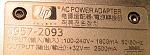
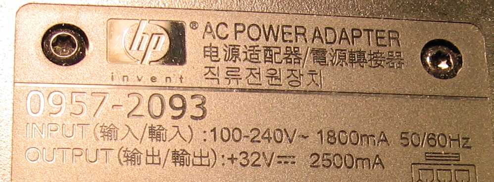
Power supply for the amplifier is made out of two HP 0957-2093 printer power supplies (32V, 2.5A output), removed from their original plastic boxes and fastened together with metal bolts, nuts and plastic isolating spacers. This way they form one unit, producing +32V and -32V needed for the LM4780. Additionally there are two banks of six 1500uF/35V low ESR noise bypass capacitors in parallel at the output of the power supply. They greatly reduce switching noise, which has a peak at a frequency of around 30 kHz. There are also four 2200uF/35V caps soldered directly to the amp boards.
I have chosen the switching mode power supply instead of a classic 50Hz transformer because. SMPS is lighter, smaller, voltage regulated, requires less decoupling capacitance, does not produce any audible hum or spurious magnetic field around it . Its main disadvantage is production of HF noise, but, as I am going to show later, it is not a big issue when the output is properly decoupled and circuits are properly screened.
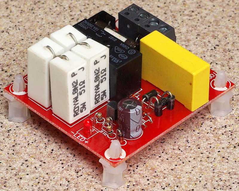
All the SMPSes used inside the device create a large capacitance which loads rapidly when the power is switched on creating strong initial current draw. To avoid sticking of the power switch contacts or fuse blowing, I used classic soft-start circuit:

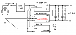
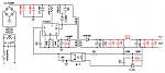
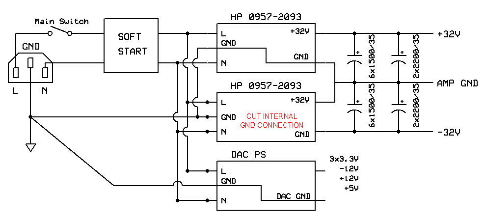
The general schematics of power supplies for the whole device. Notice that all grounds meet in one point and this is also the point of connection to the housing:
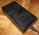
Original HP brick:
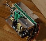
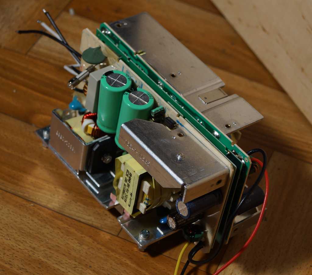
The two HP internals mounted together as a unit:
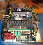
And the unit placed inside the housing (red board is the soft-start):
DAC power supply similarly uses three, off-the-shelf SMPSes as primary power sources. These are slightly modified, mainly to reduce the HF noise. The electrolytic caps have been bypassed with ceramic and foil ones, the output choke has been enlarged, the transformers have been shielded. The output voltage has been risen from initial 12V to 15V by adding one 39K resistor, visible in red on the schematics. Higher voltage is needed , because there is voltage drop across gyrators, and also LT 1763s need some drop to operate. There are three inductance gyrators (TIP122 Darlington with passive elements) for further reduction of the HF noise. and two LT1763 for (+/-12V) I?V stage op-amps, another LT1763 pre-regulates +5V which is the base power for the whole dac board. This is supplied to another LT1763 lowering voltage further to 3.3V and then feeding it to ADP151 on the DAC board (1.2V VDD). The 5V base power also supplies two ADM71150 providing low noise 3.3V DVCC and AVCC for the ES9018 chip.
Modified THX203 based SMPS schematics (added components in red):
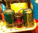
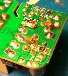
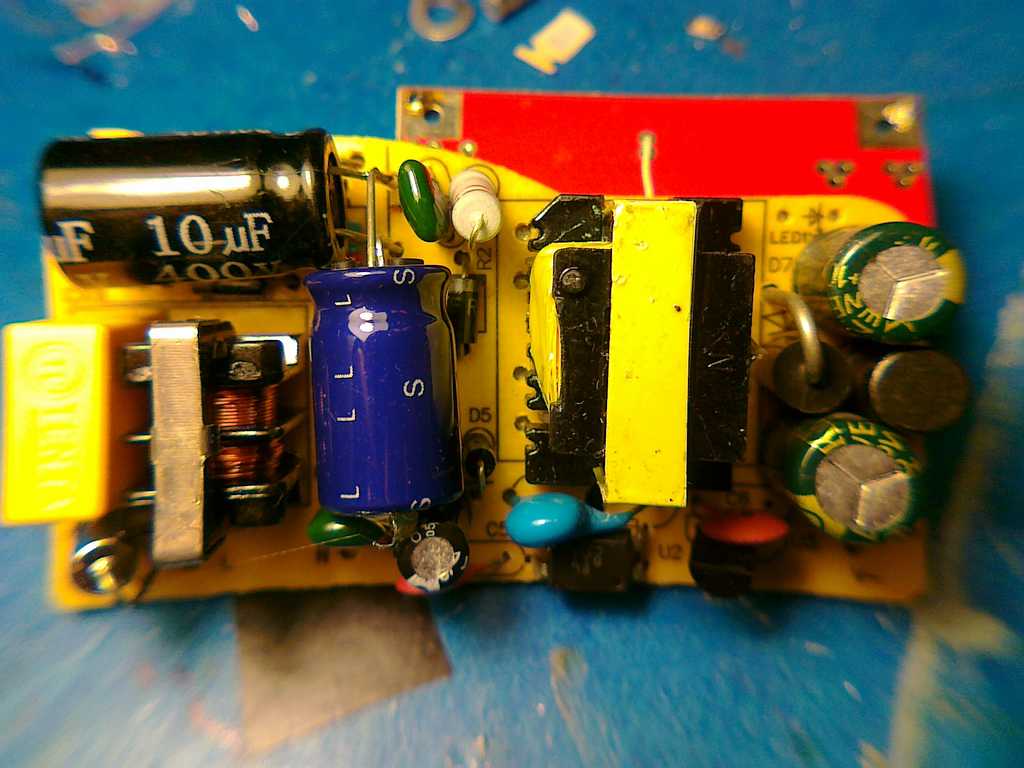
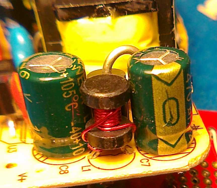
Modifications done to SMPS:

Power supply for the amplifier is made out of two HP 0957-2093 printer power supplies (32V, 2.5A output), removed from their original plastic boxes and fastened together with metal bolts, nuts and plastic isolating spacers. This way they form one unit, producing +32V and -32V needed for the LM4780. Additionally there are two banks of six 1500uF/35V low ESR noise bypass capacitors in parallel at the output of the power supply. They greatly reduce switching noise, which has a peak at a frequency of around 30 kHz. There are also four 2200uF/35V caps soldered directly to the amp boards.
I have chosen the switching mode power supply instead of a classic 50Hz transformer because. SMPS is lighter, smaller, voltage regulated, requires less decoupling capacitance, does not produce any audible hum or spurious magnetic field around it . Its main disadvantage is production of HF noise, but, as I am going to show later, it is not a big issue when the output is properly decoupled and circuits are properly screened.
All the SMPSes used inside the device create a large capacitance which loads rapidly when the power is switched on creating strong initial current draw. To avoid sticking of the power switch contacts or fuse blowing, I used classic soft-start circuit:
The general schematics of power supplies for the whole device. Notice that all grounds meet in one point and this is also the point of connection to the housing:
Original HP brick:

The two HP internals mounted together as a unit:
And the unit placed inside the housing (red board is the soft-start):

DAC power supply similarly uses three, off-the-shelf SMPSes as primary power sources. These are slightly modified, mainly to reduce the HF noise. The electrolytic caps have been bypassed with ceramic and foil ones, the output choke has been enlarged, the transformers have been shielded. The output voltage has been risen from initial 12V to 15V by adding one 39K resistor, visible in red on the schematics. Higher voltage is needed , because there is voltage drop across gyrators, and also LT 1763s need some drop to operate. There are three inductance gyrators (TIP122 Darlington with passive elements) for further reduction of the HF noise. and two LT1763 for (+/-12V) I?V stage op-amps, another LT1763 pre-regulates +5V which is the base power for the whole dac board. This is supplied to another LT1763 lowering voltage further to 3.3V and then feeding it to ADP151 on the DAC board (1.2V VDD). The 5V base power also supplies two ADM71150 providing low noise 3.3V DVCC and AVCC for the ES9018 chip.
Modified THX203 based SMPS schematics (added components in red):

Modifications done to SMPS:

Total Comments 0


