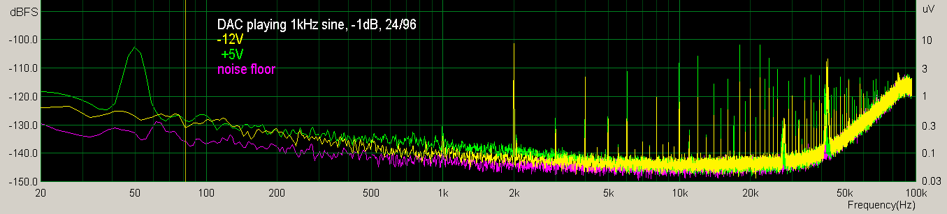
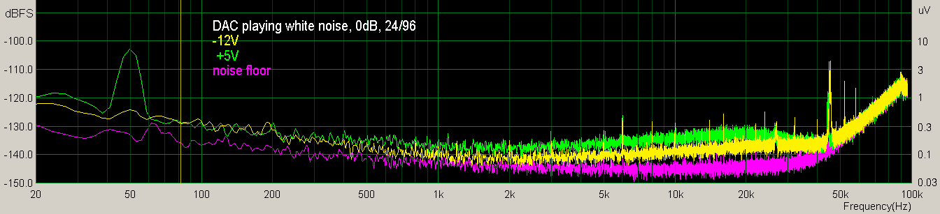
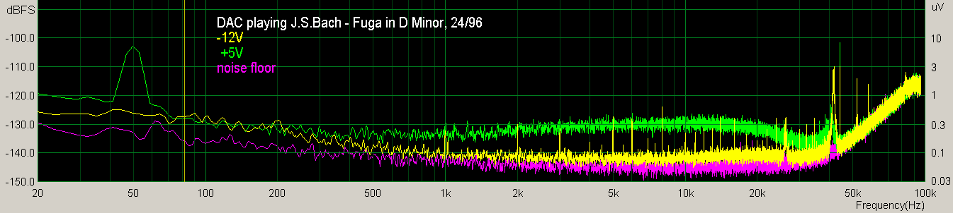
Go Back   Home > Forums > Blogs > Maciej Czerwinski

Uncategorized Entries with no category
Old

Eltax Liberty 5+ modification

Posted 10th February 2015 at 09:22 PM by Maciej Czerwinski

I bought these speakers in 2000. I was unhappy with the way they reproduce low frequencies. I decided to add a subwoofer. I used the fact that the lower part of the housing of the speaker is empty and isolated from the upper part in which the speakers operate. I cut a hole in the side of the bottom part and installed a 25 cm driver.
Click image for larger version

Name:	dziura.jpg
Views:	337
Size:	18.0 KB
ID:	1551
It is Vestra PW-250-2154 woofer.
It has a 19 cm coated-paper membrane, foam external suspension, extruded metal sheet basket, ventilated 4.5 cm coil, the diameter of the magnet is 12 cm, 80 W, 4 ohms, the self-resonance (Fs) at 27 Hz.
Click image for larger version

Name:	glosnik2.jpg
Views:	461
Size:	18.2 KB
ID:	1552
I damped the interior of this newly created enclosure space with bitumen mat and felt glued to the walls and filled it with fleece. I cut out the rear wall from the top part of the enclosure. Inserted a reinforcing crossbars into the lower and upper housing. The upper part of the housing is entirely filled with a damping material (with fleece filled pillow, which...
Attached Thumbnails
Click image for larger version

Name:	przod.jpg
Views:	1920
Size:	61.2 KB
ID:	1553   Click image for larger version

Name:	tyl.jpg
Views:	2445
Size:	65.8 KB
ID:	1554   Click image for larger version

Name:	stara_zwrotn.jpg
Views:	257
Size:	23.5 KB
ID:	1555   Click image for larger version

Name:	zwrot1.jpg
Views:	352
Size:	112.3 KB
ID:	1556   Click image for larger version

Name:	zwrot2.jpg
Views:	854
Size:	93.0 KB
ID:	1557  

Click image for larger version

Name:	zwrotn_bas.jpg
Views:	314
Size:	96.9 KB
ID:	1558   Click image for larger version

Name:	zwrotn_schem.png
Views:	332
Size:	4.9 KB
ID:	1559  
diyAudio Member
Posted in Uncategorized
Views 3471 Comments 0 Maciej Czerwinski is offline
Old

Eltax Liberty 5+ modification part2

Posted 10th February 2015 at 09:16 PM by Maciej Czerwinski

All measurements done with Panasonic WM-61A microphone with Eric Wallin preamplifier and E-MU0202. Single driver frequency response without any crossover. The microphone is located at a distance of 1 meter from the driver on its main axis.
Vifa 3075 dome tweeter:
Click image for larger version

Name:	3075.png
Views:	270
Size:	4.4 KB
ID:	1560
Vifa TC 3520 woofer:
Click image for larger version

Name:	3520_baffle.png
Views:	267
Size:	6.8 KB
ID:	1561
Vestra PW-250-2154 woofer with it's crossover, microphone located 10 cm from the driver:
Click image for larger version

Name:	bas_z_bliska.png
Views:	241
Size:	17.6 KB
ID:	1562

The complete speaker after modification.
Measurements done at my usual listening spot, 2.5 m from the speaker, microphone positioned 50 cm closer, farther, higher and lower around the spot. Obtained frequency response curves are strongly smoothed, because changing the position of the microphone produces a large change in the jags of the curve, and I wanted to show invariant features of the speaker frequency response:
Click image for larger version

Name:	lewa_tapczan_rozne_polozenia_mikrofonu.png
Views:	240
Size:	12.6 KB
ID:	1563
It is pretty flat, and the bass is very nice now.
...
diyAudio Member
Posted in Uncategorized
Views 608 Comments 0 Maciej Czerwinski is offline
Old

DIY ES9018 DAC + LM4780 AMP

Posted 6th January 2015 at 12:30 PM by Maciej Czerwinski

Finished, front:
Click image for larger version

Name:	caly_przod_obud.jpg
Views:	439
Size:	22.0 KB
ID:	1468
back:
Click image for larger version

Name:	caly_tyl_obud.jpg
Views:	348
Size:	23.2 KB
ID:	1469
what's inside:
Click image for larger version

Name:	CALY_OPIS.jpg
Views:	1914
Size:	87.9 KB
ID:	1470
This device is built around DIYINHK ES9018 DAC board, with USB to I2C CM6631 converter, also from DIYINHK. USB is the only signal input. Power amplifier uses two LM4780 chips, one per channel in mono-parallel configuration. Power supply for the amplifier is made out of two HP printer power supplies. DAC power supply is more complex, but also uses three, a little bit modified, 12V supplies, wall plug in type, general use ones. Volume regulation (attenuation to be exact) is entirely digital, provided by ES9018 dac chip. It is controlled by PIC16F84 microcontroller via I2C. There is also 3-digit attenuation level display and rotary encoder is used for setting the attenuation level. Details are described in next posts.
diyAudio Member
Posted in Uncategorized
Views 1028 Comments 0 Maciej Czerwinski is offline
Old

DIY ES9018 DAC + LM4780 AMP Details part 1

Posted 6th January 2015 at 12:30 PM by Maciej Czerwinski

DAC:
On the DIYINHK DAC board we can find ES9018 chip and ADP151 1.2V linear regulator (VDD) factory soldered. You have to populate the rest of the board yourself. I have soldered:
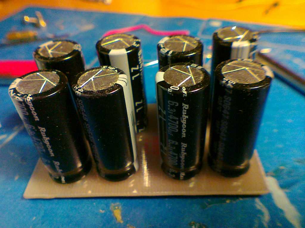
- ceramic and electrolytic noise filtering bypass capacitors,
- various resistors, mostly in the I/V stage,
- I/V stage op-amps (4xAD797)
- output signal low-pass filter capacitors.
The board is designed for 6 op-amps with SE output. I wanted differential output, so I have done some modifications, following the ES9018 demo board datasheet.

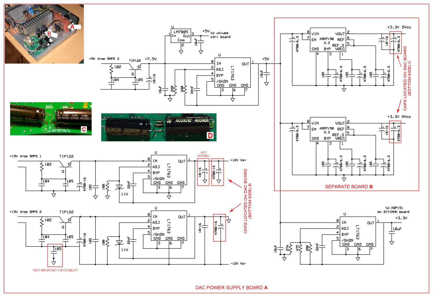
The I/V stage and power amp schematics (one channel):
Click image for larger version

Name:	av_amp_sch.jpg
Views:	2474
Size:	67.6 KB
ID:	1478
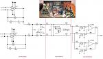
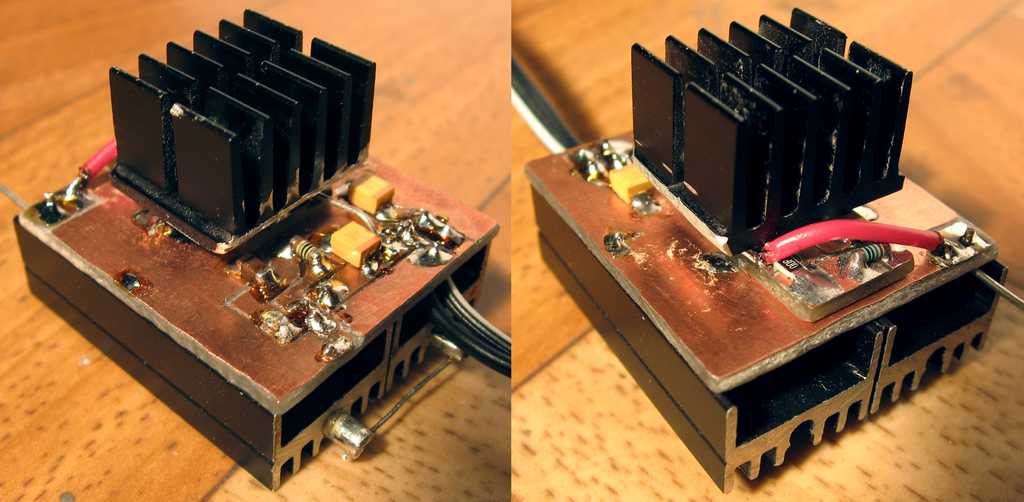
When the main power is switched off, the relay shorts the power amp inputs in order to avoid oscillations, generated by I/V stage during discharge of its power supply bypass capacitors, to pass to the power amp.
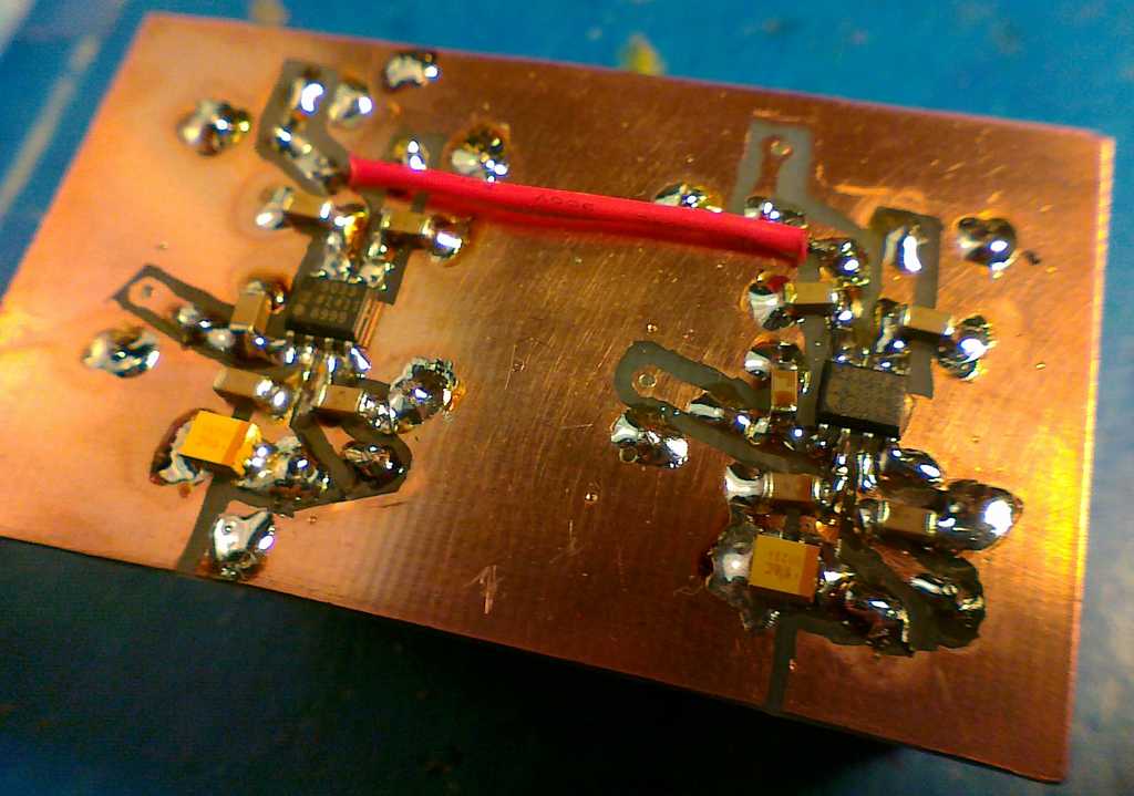
A/V stage section of the DAC board – one channel, ES9018 chip side (top side in my case)....
Attached Thumbnails
Click image for larger version

Name:	dac_zbliz_pwzm.jpg
Views:	966
Size:	113.2 KB
ID:	1479   Click image for larger version

Name:	dac_zbliz_pwzm_spod.jpg
Views:	663
Size:	63.0 KB
ID:	1480  
diyAudio Member
Posted in Uncategorized
Views 1230 Comments 0 Maciej Czerwinski is offline
Old

DIY ES9018 DAC + LM4780 AMP Details part 2

Posted 6th January 2015 at 12:29 PM by Maciej Czerwinski

POWER AMPLIFIER:
It works in parallel configuration in order to drive 4 ohm speakers easier. Such configuration has quite low input impedance, around 5kOhm, and low gain of 3.7. This, with the 3x20k input signal resistor divider, gives the maximum output power of only 1W for single sine.
The two pairs of 100k, multi-turn potentiometers set the symmetry of each amplifier. It has to be adjusted manually. In order to do it, you have to supply in-phase (single ended) signal to the input of each amplifier and turn the potentiometers until the signal at the output of each amplifier drops to zero (or rather goes below the noise floor). Unfortunately it also affects the voltage at the amplifier output. There is a lot of trial-and-error work needed to achieve zero signal and zero volts at the output. It is good to do it separately for each of the amplifier from the pair by unsoldering output 0.1 ohm resistors. Signal generator and frequency spectrum meter comes in handy for this...
Attached Thumbnails
Click image for larger version

Name:	caly_wzm.jpg
Views:	270
Size:	82.5 KB
ID:	1481   Click image for larger version

Name:	wzm_zbliz.jpg
Views:	355
Size:	99.7 KB
ID:	1482   Click image for larger version

Name:	wzm_zbliz_spod.jpg
Views:	245
Size:	124.3 KB
ID:	1483  
diyAudio Member
Posted in Uncategorized
Views 589 Comments 0 Maciej Czerwinski is offline
Old

DIY ES9018 DAC + LM4780 AMP Details part 3

Posted 6th January 2015 at 12:29 PM by Maciej Czerwinski

POWER SUPPLIES
Power supply for the amplifier is made out of two HP 0957-2093 printer power supplies (32V, 2.5A output), removed from their original plastic boxes and fastened together with metal bolts, nuts and plastic isolating spacers. This way they form one unit, producing +32V and -32V needed for the LM4780. Additionally there are two banks of six 1500uF/35V low ESR noise bypass capacitors in parallel at the output of the power supply. They greatly reduce switching noise, which has a peak at a frequency of around 30 kHz. There are also four 2200uF/35V caps soldered directly to the amp boards.
I have chosen the switching mode power supply instead of a classic 50Hz transformer because. SMPS is lighter, smaller, voltage regulated, requires less decoupling capacitance, does not produce any audible hum or spurious magnetic field around it . It’s main disadvantage is production of HF noise, but, as I am going to show later, it is not a big issue when the output is properly...
Attached Thumbnails
Click image for larger version

Name:	softstart.jpg
Views:	1327
Size:	73.7 KB
ID:	1484   Click image for larger version

Name:	zas_ogolny_sch.png
Views:	536
Size:	10.1 KB
ID:	1485   Click image for larger version

Name:	zas_hp1.jpg
Views:	229
Size:	71.5 KB
ID:	1486   Click image for larger version

Name:	zas_hp2.jpg
Views:	168
Size:	59.3 KB
ID:	1487   Click image for larger version

Name:	zas_wzm1.jpg
Views:	329
Size:	59.0 KB
ID:	1488  

Click image for larger version

Name:	caly_str_lewa.jpg
Views:	590
Size:	118.9 KB
ID:	1489   Click image for larger version

Name:	sps_THX203.png
Views:	2649
Size:	16.3 KB
ID:	1490   Click image for larger version

Name:	zas_dac3.jpg
Views:	217
Size:	63.2 KB
ID:	1491   Click image for larger version

Name:	zas_dac4.jpg
Views:	232
Size:	63.8 KB
ID:	1492   Click image for larger version

Name:	zas_dac2.jpg
Views:	211
Size:	103.4 KB
ID:	1493  

diyAudio Member
Posted in Uncategorized
Views 1811 Comments 0 Maciej Czerwinski is offline
Old

DIY ES9018 DAC + LM4780 AMP Details part 4

Posted 6th January 2015 at 12:28 PM by Maciej Czerwinski

The post-regulation schematics:
Click image for larger version

Name:	dac_zas_sch.jpg
Views:	2893
Size:	125.2 KB
ID:	1494
ThreeTHX203 SMPS boards soldered to the main power supply board. There are also additional 230V input filter, output bypass caps and gyrator’s TIP122 visible:
Click image for larger version

Name:	dac_zas_3zi.jpg
Views:	1505
Size:	97.7 KB
ID:	1495

The other side of the main board – LT1763 regulators, 5V main power daughterboard with heatsinks:
Click image for larger version

Name:	zas_dac_all.jpg
Views:	573
Size:	65.3 KB
ID:	1496

Details of the 5V main power daughterboard. The top heatsink is for the LM1763, the two on the bottom are for TIP122 (gyrator) and LM7805 (5V for volume controller):
Click image for larger version

Name:	zas_dac_5V.jpg
Views:	502
Size:	51.6 KB
ID:	1497

ADM7150 3.3V regulators on separate board with Rubycon ZL 4700uF/6.3V low ESR bypass caps (board bottom):
Click image for larger version

Name:	zas_dac12.jpg
Views:	411
Size:	62.1 KB
ID:	1498

(board top):
Click image for larger version

Name:	zas_dac14.jpg
Views:	220
Size:	62.0 KB
ID:	1499

This photos show the how dac power supply is mounted inside the housing:
Click image for larger version

Name:	caly_str_prawa.jpg
Views:	449
Size:	93.9 KB
ID:	1500Click image for larger version

Name:	caly_prawa_z_gory.jpg
Views:	288
Size:	88.5 KB
ID:	1501
diyAudio Member
Posted in Uncategorized
Views 2076 Comments 0 Maciej Czerwinski is offline
Old

DIY ES9018 DAC + LM4780 AMP Details part 5

Posted 6th January 2015 at 12:28 PM by Maciej Czerwinski
Updated 6th January 2015 at 12:36 PM by Maciej Czerwinski

Graphs showing the dac power supply output noise. You can see the SMPS switching frequency noise peaks at 26kHz and 32kHz. Their frequency rise a little when more current is drawn from the supply. It seems that the dac playing 1kHz is an example of the hardest load to regulate for the supply:
Click image for larger version

Name:	smps_vs_noise_floor3.png
Views:	319
Size:	15.6 KB
ID:	1502
Click image for larger version

Name:	smps_vs_noise_1khz.png
Views:	209
Size:	16.8 KB
ID:	1503
Click image for larger version

Name:	smps_vs_noise_wn.png
Views:	157
Size:	17.3 KB
ID:	1504
Click image for larger version

Name:	smps_vs_noise_fuga.png
Views:	144
Size:	16.9 KB
ID:	1505


VOLUME CONTROLLER:
It’s a PIC16F84 running a program written by me. It reads rotary encoder and accordingly writes values, via I2C, to the ES9018 attenuation registers. It writes single value to all 8 registers every tick of the encoder. After 10 seconds of no encoder activity, it stores the value to the internal EEPROM of the microcontroller.
The controller board has its own 3.3V regulator, the display board has 1.8V regulator for LEDs
The display module is a separate I2C dumb reader. It catches the attenuation values transmitted...
Attached Thumbnails
Click image for larger version

Name:	ES9018_I2C_PIC16LF84_Volume_simple.png
Views:	957
Size:	12.9 KB
ID:	1506   Click image for larger version

Name:	vol_disp.png
Views:	497
Size:	69.8 KB
ID:	1507   Click image for larger version

Name:	reg_glosn3.jpg
Views:	210
Size:	52.3 KB
ID:	1508   Click image for larger version

Name:	reg_glosn1.jpg
Views:	213
Size:	81.2 KB
ID:	1509   Click image for larger version

Name:	reg_glosn2.jpg
Views:	127
Size:	51.2 KB
ID:	1510  

Click image for larger version

Name:	reg_glosn4.jpg
Views:	137
Size:	161.2 KB
ID:	1511  
diyAudio Member
Posted in Uncategorized
Views 937 Comments 0 Maciej Czerwinski is offline
Old

DIY ES9018 DAC + LM4780 AMP Details part 6

Posted 6th January 2015 at 12:28 PM by Maciej Czerwinski
Updated 6th January 2015 at 06:18 PM by Maciej Czerwinski

HOUSING:
Typical steel box consists of four pieces bolted together. Dimensions: 440 x 100 x 255 mm (W x H x D). Notice the "Acqua di Gio" volume knob

Click image for larger version

Name:	caly_przod_obud.jpg
Views:	214
Size:	22.0 KB
ID:	1519
Bottom piece. I made two holes to let air flow through power amp heatsinks. There are corresponding holes in the top piece. The black plastic pieces are heatsink mountings:
Click image for larger version

Name:	dno.jpg
Views:	257
Size:	57.8 KB
ID:	1512
Click image for larger version

Name:	dno2.jpg
Views:	347
Size:	45.1 KB
ID:	1518
Top cover and side walls form one piece. I glued same aluminum mesh into heatsink airflow holes in order to protect the inside of the housing.
Click image for larger version

Name:	pokr_spod.jpg
Views:	289
Size:	40.6 KB
ID:	1513

Detailed view of front piece inner side. Display protecting glass cut out of old picture frame and painted with red transparent paint. Total DIY:
Click image for larger version

Name:	szybka_wysw.jpg
Views:	336
Size:	117.7 KB
ID:	1514

MEASUREMENTS:
Output of the power amplifier loaded with 3.9Ohm resistor, connected to Left line input of the E-MU 0202 with two 10uF unipolar electrolytic caps. E-MU...
Attached Thumbnails
Click image for larger version

Name:	pomiar_wzm.jpg
Views:	312
Size:	49.9 KB
ID:	1515   Click image for larger version

Name:	thd_n_gotowy_dac_amp.png
Views:	265
Size:	7.9 KB
ID:	1516   Click image for larger version

Name:	imd.png
Views:	162
Size:	9.7 KB
ID:	1517   Click image for larger version

Name:	pasmo.png
Views:	153
Size:	3.8 KB
ID:	1520  
diyAudio Member
Posted in Uncategorized
Views 949 Comments 0 Maciej Czerwinski is offline

New To Site? Need Help?
Copyright ©1999-2017 diyAudio