Go Back   Home > Forums > Blogs

Old

An LC filter for supplying a line stage

Posted 19th February 2016 at 01:33 AM by abraxalito
Updated 22nd February 2016 at 01:51 AM by abraxalito

I've designed LC filters for classAB amp power supplies before - for those applications iron powder toroids work fine for the Ls. However for the power supply in my latest DAC design I wanted more supply rejection and this calls for higher value inductors - in the tens of mH. Creating a 10mH inductor on a toroid takes way too long and is hugely fiddly as the wire length needed is substantial and I don't have any specialized winding machine. So toroids are really out of the question at such values.

I have some largeish inductors in the right range wound on bobbin cores but when I checked the DCR it was a little high, 20ohms or so. As I might need up to 100mA, a 2V drop is too great. In any case, in LTspice this resulted in rather an overdamped response - what I really needed is something in the range 1 to 2 ohms. The solution seemed to be use ferrite cores of the kind normally used to make transformers. Which means breaking a kind of informal rule I made for myself about not...
Attached Thumbnails
Click image for larger version

Name:	4thLC.jpg
Views:	263
Size:	22.4 KB
ID:	1802   Click image for larger version

Name:	P60222-085432.jpg
Views:	230
Size:	399.1 KB
ID:	1808  
abraxalito's Avatar
diyAudio Member
Posted in Uncategorized
Views 654 Comments 0 abraxalito is offline
Old

LTSpice filter simulation masterclass: 0 to -100dB in five easy steps!

Posted 19th February 2016 at 12:14 AM by rjm (RJM Audio Blog)
Updated 7th April 2016 at 06:58 AM by rjm

I've never put everything into a single LTSpice worksheet like this before: I find it fascinating. You can really pull apart a circuit to see what makes it tick, before solder ever hits the iron.

Power supply ripple, frequency response, gain, and crosstalk can be established. You can look at turn on and turn off transients, inrush currents, and conductance angle, and check peak currents in the filter capacitors. It's all there if you care to peek in and poke around.

I'm such a huge fan of LTSpice...

The only problem, really, is it is too perfect: all devices are perfectly matched, every part value is exact, and the temperature is always 25 C. Ground loops, wiring inductance, and thermal runaway do not exist. So no, of course there are no guarantees - but as a tool to get you 90% of the way there with the minimum of fuss and bother it is truly indispensable.

Actually I find the more experience you have the more useful LTSpice...
Attached Thumbnails
Click image for larger version

Name:	Crystal PSRR sim.png
Views:	2725
Size:	476.3 KB
ID:	1801   Click image for larger version

Name:	crystalFET.png
Views:	783
Size:	28.0 KB
ID:	1891  
rjm's Avatar
rjm
diyAudio Member
Views 1017 Comments 0 rjm is offline
Old

Three transistor LTspice sim

Posted 17th February 2016 at 12:10 PM by msdin

High Octane Preamp sim
Attached Files
File Type: asc Phonostage 3 transistors.asc (5.9 KB, 864 views)
diyAudio Member
Posted in Uncategorized
Views 628 Comments 3 msdin is offline
Old

jFET passive phono preamplifier circuit idea

Posted 16th February 2016 at 02:27 PM by rjm (RJM Audio Blog)
Updated 17th February 2016 at 12:51 AM by rjm

There are various tricks, like parallel input devices and active current sources, that I have avoided here in the interests of simplicity. If you want to go down that road, you can get an idea where it leads, here. Instead, the circuit below is basically a JFET version of my old 6DJ8 amp, here. A single JFET was getting me nowhere in terms of output impedance - around 10kohms! - so I moved to a compound stage buffering each amplifier with a source follower.

Noise and distortion figures look okay. The gain is only 30 dB. A bit low. The main trick is the PSRR, which is awful. The two stage circuit actually amplifies the power supply noise onto the output. So considerable effort must be put into the power supply regulation and filtering. I note that this is pretty much par for the course with this circuit topology where resistors are used instead of current sources on the JFET drains.

The circuit below leaves out the usual RC filter inserted between the power supply...
Attached Thumbnails
Click image for larger version

Name:	RJM jfet phono.png
Views:	716
Size:	36.4 KB
ID:	1796   Click image for larger version

Name:	RJM jfet single stage.png
Views:	293
Size:	45.5 KB
ID:	1797  
Attached Files
rjm's Avatar
rjm
diyAudio Member
Views 570 Comments 0 rjm is offline
Old

Passive RIAA equalization network response calculator

Posted 16th February 2016 at 09:21 AM by rjm (RJM Audio Blog)
Updated 17th February 2016 at 12:47 AM by rjm

This Excel (2013) worksheet will help you fine tune the values of the resistors and capacitors used in the passive RIAA network found in any number of two stage tube, op amp, and FET phono stage circuits.

Excel handles complex numbers well enough now that this job isn't particularly difficult, though for simplicity the DC blocking cap (Cc) is left out of the calculation.
Attached Thumbnails
Click image for larger version

Name:	RIAA simulation.png
Views:	401
Size:	12.8 KB
ID:	1792  
Attached Files
File Type: zip Passive RIAA equalization network response calculator.zip (377.1 KB, 131 views)
rjm's Avatar
rjm
diyAudio Member
Posted in The Lab
Views 734 Comments 0 rjm is offline
Old

jFET phono stage | harmonic cancellation jujutsu

Posted 15th February 2016 at 07:45 AM by rjm (RJM Audio Blog)
Updated 19th February 2016 at 11:59 PM by rjm

There are lots of phono stage circuits floating around based on two jFET amplifier stages and a passive RIAA network. I'm not sure who did what first, but there's the Boozehound, LePacific, and of course Salas versions.

Setting aside concerns about the ripple rejection**, today I'd just like to focus on the distortion and noise of the circuit itself. The passive RIAA stage is a large obstacle. It attenuates the signal substantially at all but treble frequencies, and it generally presents a large series impedance - both of which tends to increase circuit noise.

The jFET themselves meanwhile are a fine balance between low current, low noise operation with high distortion, or running at high current, high noise, with low distortion. Circuit gain must be paid for meanwhile with added distortion since the two stage design struggles to manage 40 dB.

After spending some time in LTSpice with this, I realized it was the proverbial rock and hard place...
Attached Thumbnails
Click image for larger version

Name:	jfet phono B.png
Views:	336
Size:	312.3 KB
ID:	1789  
Attached Files
File Type: asc Crystal P.asc (3.3 KB, 115 views)
rjm's Avatar
rjm
diyAudio Member
Posted in The Lab
Views 518 Comments 0 rjm is offline
Old

Hiphonics Zxi 1008 amp repairs almost completed

Posted 9th February 2016 at 11:38 AM by tscr2015

The customers original problem with this amp was that it had no sound on one of the two channels, after replacing various components in the amp section and the power supply section it turns out that all it was, was a bad crossover selector switch. The contacts had broken on the inside of the switch. Sourcing this switch is a problem because most companies carry it but you have to buy like 100 or more at $.40/ea. Did find that I can get one from Mouser electronics next month. So in the mean time for testing purposes I hard wired the contacts in the switch together with solder until I can get a new switch.

Stay tuned....
diyAudio Member
Posted in Uncategorized
Views 495 Comments 0 tscr2015 is offline
Old

Headphone amplifier ground. Where to make the chassis connection?

Posted 2nd February 2016 at 08:11 AM by rjm (RJM Audio Blog)
Updated 24th February 2016 at 02:02 AM by rjm

The discussion thread at the headphone forum is here, but I wanted to throw out the problem to the general blog-reading community here at diyaudio to see if anyone can nail this.

The earthed chassis (light blue) must connect to the circuit common i.e. "ground" (pale green). I do not know where the best place on the circuit ground is to tie that connection.

Suggestions please!

(COM and GND are completely equivalent pads on the circuit board, while IN- and OUT- also pads on the board but physically further away on the ground plane.)

****

Answer: as long as it connects at one point only, or the same point of both channels, it doesn't seem to matter at all. I have it connected at the ground tab of the headphone jack and that seems to be as good as anywhere.

****

The noise was in fact magnetic interference emanating from the transformers. Grounding layout changes / electrostatic...
Attached Thumbnails
Click image for larger version

Name:	Sapphire ground.png
Views:	962
Size:	32.5 KB
ID:	1775   Click image for larger version

Name:	DSC_5322b sm.jpg
Views:	2100
Size:	846.7 KB
ID:	1777   Click image for larger version

Name:	DSC_5407 sm.jpg
Views:	1933
Size:	748.4 KB
ID:	1780   Click image for larger version

Name:	Z-reg sim.png
Views:	592
Size:	273.4 KB
ID:	1782   Click image for larger version

Name:	IMGP6318sm.jpg
Views:	890
Size:	301.3 KB
ID:	1783  

Click image for larger version

Name:	permalloy.png
Views:	286
Size:	51.1 KB
ID:	1809  
Attached Files
rjm's Avatar
rjm
diyAudio Member
Views 1427 Comments 7 rjm is offline
Old

EPSUX3v2 High performance power supply group buy list

Posted 31st January 2016 at 02:06 PM by Frex
Updated 2nd March 2016 at 05:34 PM by Frex

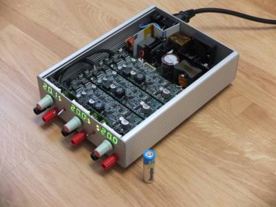
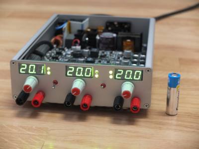
EPSUX3V2

High performance 160W triple outputs Lab power supply
PCB GROUP BUY


Click the image to open in full size. Click the image to open in full size.


Frex, the 31 Junary, 2016.


Hello all,

I opened here a new blog page to replace the dedicated wiki page previously
made for this group buy list.
The DIYaudio wiki is unavailable for weeks now and that will take some time
to be re-opened. So for this reason i move the group buy here on this new blog.
I will probably also take advantage of this new blog to share many others things.

Until now, 12 pre-order are done on 25 required. We will wait end of February,
and then if we stay less than 25, i will make a new price estimation for a lower batch.

Frex


The buyers list you will find below can only be...
Attached Files
File Type: pdf EPSUX3V2.1_sch.pdf (487.7 KB, 254 views)
File Type: pdf EPSUX3REGV1.1_sch.pdf (146.2 KB, 348 views)
File Type: pdf EPSUX3V2_Manual_Beta.pdf (771.7 KB, 184 views)
File Type: pdf EPSUX3V2_FULLBOM_IndA.pdf (105.7 KB, 213 views)
diyAudio Member
Posted in Uncategorized
Views 834 Comments 0 Frex is offline
Old

What are "Ground Boxes"?

Posted 24th January 2016 at 12:48 AM by rjm (RJM Audio Blog)

Ladies and gentlemen, please try to keep a straight face while browsing the following link.

https://www.entreq.com/products/ground-boxes-17667704

I'm not sure whether its possible to build a passive, permanent device that dissipates/neutralizes electrical charge. But the scientist part of me finds the claims that you can interesting.

Static electricity will eventually dissipate by attracting counter ions from the air. This happens more quickly if the humidity is high.

So seriously, if you just stuck a wire into a bucket of dirt, how much "earthing" would that actually provide? Is there any way to amplify that effect by using special materials or even passive electrical components?
rjm's Avatar
rjm
diyAudio Member
Views 745 Comments 2 rjm is offline

New To Site? Need Help?
Copyright ©1999-2017 diyAudio