Go Back   Home > Forums > Blogs

Old

A one-dimensional two-channels stereophonic standard

Posted 7th February 2017 at 02:47 PM by Grasso789
Updated 27th June 2017 at 09:25 AM by Grasso789

Recently it has been archieved to capture, store, propagate and play back audio with the full human hearing frequency range (16 to 16000 Hz) and contrast (7 Bel). Still, if a big sound source or several sound sources at once are the matter of content, such play-back sounds artificial, because all is emitted from one acoustic source. In order to hear, what is going on, we use both ears simultaniously, turn our head in different directions and will detect the electro-acoustic device.

While an indetectable electro-acoustic reproduction incorporated six microphones, storage and transmission channels and a house-sized sphere covered by loudspeakers on the inside and containing the listener, we can help imagination at least a little bit by introducing sonic differences between left and rite. We also want this stereo, after Greek stereos shape, to integrate thoroly and easily with already existing mono electro-acoustics. We may double transmission and storage channels, for example...
diyAudio Member
Posted in Uncategorized
Views 553 Comments 2 Grasso789 is offline
Old

Getting Distortion Down

Posted 1st February 2017 at 08:59 AM by SyncTronX
Updated 1st February 2017 at 07:25 PM by SyncTronX

Over in the Low-distrotion, Audio-range,
Oscillator thread (LINK) some posts
about getting lower distortion before taking
the measurement of a DUT (Device Under Test).

Our own RNMarsh posted some good results
running his Panasonic through a miniDSP
box configured as a Low Pass Filter.

He had good results. So I thought and told him
so, and suggested he might get better results doing a band pass filter.

So instead of doing my diode homework for
my Solid State Devices class, I thought I'd
better check, that is put up for shut up.

So, I did and here is what I discovered:
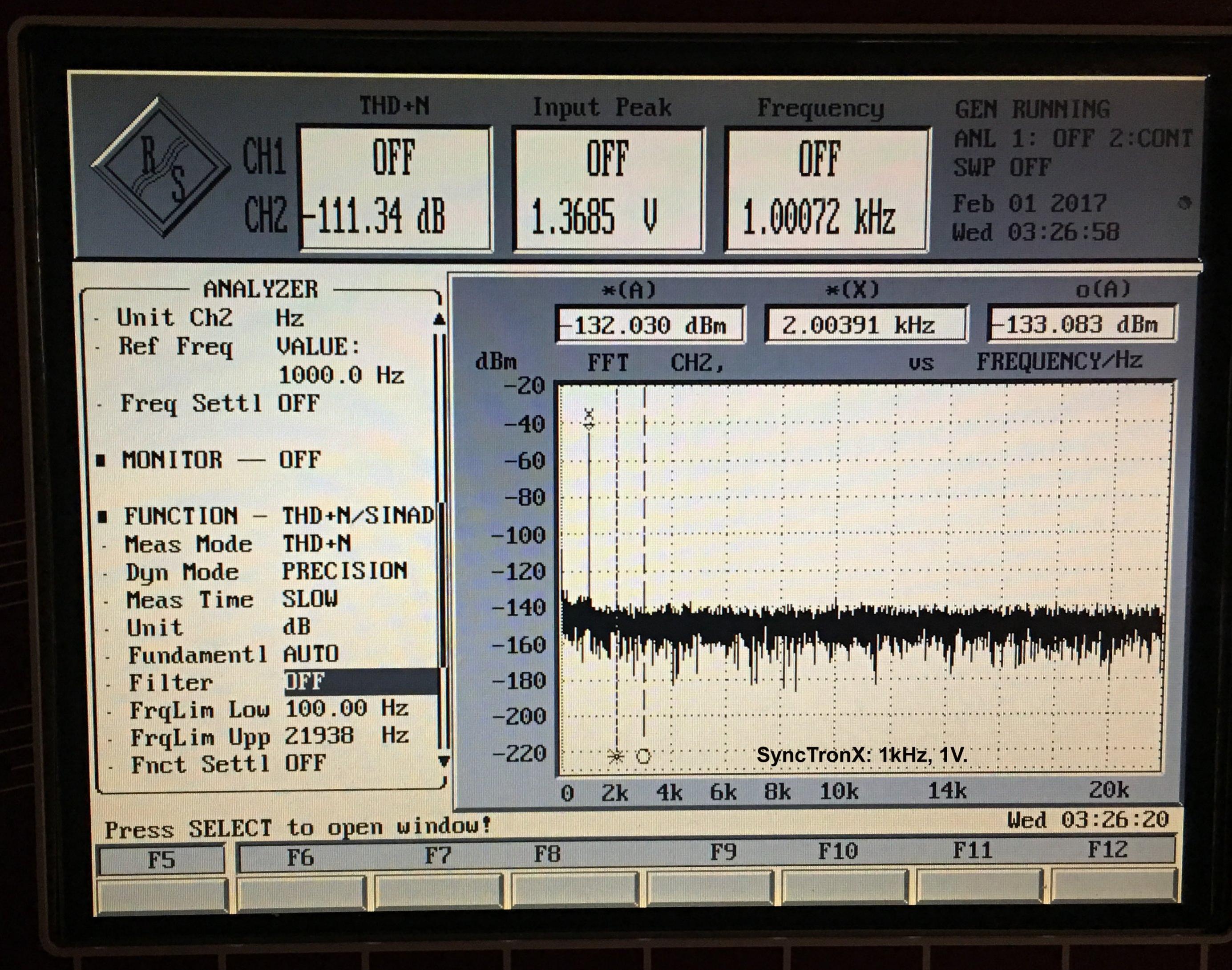
Before filtering:
Click the image to open in full size.

https://www.diyaudio.com/forums/attac...r-baseline.jpg...
SyncTronX's Avatar
diyAudio Member
Posted in Uncategorized
Views 417 Comments 0 SyncTronX is offline
Old

For Sale - Reference DAC PSU for Red Baron / Tube-I-zator

Posted 28th January 2017 at 11:16 AM by dvb projekt
Updated 8th February 2017 at 06:19 AM by dvb projekt

Reference DAC PSU
for Red Baron / Tube-I-zator

Click the image to open in full size.

Click the image to open in full size.

Click the image to open in full size.

Click the image to open in full size.Click the image to open in full size.

Click the image to open in full size.

Custom made "Galaxy" housing with 10mm front panel from modushop.biz

Custom made Transformer with double C-cores, made for Vacuumschmelze Germany for Siemens military equipment

Tube-Rectifier circuit (6106/GZ34 or equivalent) with High-End Parts for B+ of the Tube-I-zator

The C-L-C-R-C Network with no electrolytic caps!

Yamamoto Teflon socket
...
dvb projekt's Avatar
diyAudio Member
Posted in Offer
Views 832 Comments 0 dvb projekt is offline
Old

A power amplifier.

Posted 19th January 2017 at 11:37 PM by rjm (RJM Audio Blog)
Updated 22nd May 2017 at 02:26 AM by rjm

This is an unfinished design idea.

*****

Another request.

The Sapphire4 and Unity (H) boards were based on the 47 Labs Treasure 0347 amplifier circuit, and the original was not so far away that I couldn't "de-modify" the Unity (H) board back to what is essentially a 0347 (but with neither the original transistors nor the original resistor values).

I changed just about all the resistor values slightly for one reason or another, and changed all the transistor types. I've run my own simulations to check my version basically works as it should. Output BD135(39),136(40) are shown on the schematic as being leftovers from my headphone design, they will work to play music but to meet high current output specifications something bigger in TO-220 or similar thermal package will be needed.

As I hope you can see from the circuit schematic, the design - for a power amplifier - is unconventional. There is no feedback...
Attached Thumbnails
Click image for larger version

Name:	pcb-unity47-10a-brd.png
Views:	270
Size:	16.4 KB
ID:	2235   Click image for larger version

Name:	Unity47-10a.png
Views:	222
Size:	185.2 KB
ID:	2236   Click image for larger version

Name:	pcb-unity47-10a1-sch.png
Views:	549
Size:	19.0 KB
ID:	2239  
Attached Files
File Type: zip unity47-10a.zip (97.3 KB, 94 views)
File Type: asc Unity 10a (H) 47 mod.asc (5.5 KB, 202 views)
rjm's Avatar
rjm
diyAudio Member
Views 656 Comments 2 rjm is offline
Old

Phono Stage Cartridge Loading Auxiliary PCB

Posted 18th January 2017 at 07:02 AM by rjm (RJM Audio Blog)
Updated 19th January 2017 at 05:33 AM by rjm

By request.

Simple 4 option loading for MC or MM cartridges. Stereo board, 80x50 mm. Part of the "useful elements" series.

Inputs are bidirectional (pass through), the signal only has to be connected to one set to function. What more loading choices? Use two boards!
Attached Thumbnails
Click image for larger version

Name:	pcb-swicth-10a-sch.png
Views:	261
Size:	6.0 KB
ID:	2231   Click image for larger version

Name:	pcb-swicth-10a-brd.png
Views:	192
Size:	4.7 KB
ID:	2232   Click image for larger version

Name:	switch-10a.png
Views:	182
Size:	94.0 KB
ID:	2233  
Attached Files
rjm's Avatar
rjm
diyAudio Member
Views 372 Comments 0 rjm is offline
Old

Dual Bridge Rectifier PCB

Posted 18th January 2017 at 05:33 AM by rjm (RJM Audio Blog)
Updated 1st July 2017 at 11:50 PM by rjm

I'm sure there are dozens of people on diyaudio who could do up this layout, but hey, it was a super-quick modification of the cartridge loading board I was doing anyway ... so to continue the series of 50x80mm "useful elements" boards, here is a dual bridge rectifier board for a transformer with two secondaries.

It will work with just about all of my projects, or anyplace you want to have the diodes separate from the rest of the circuit.

These are available on my web page.
Attached Thumbnails
Click image for larger version

Name:	pcb-bridge-10a-sch.png
Views:	228
Size:	4.9 KB
ID:	2226   Click image for larger version

Name:	pcb-bridge-10a-brd.png
Views:	192
Size:	5.2 KB
ID:	2227   Click image for larger version

Name:	bridge-10a.png
Views:	191
Size:	89.6 KB
ID:	2228   Click image for larger version

Name:	DBRB.png
Views:	6
Size:	20.1 KB
ID:	2416  
Attached Files
File Type: zip pcb-bridge-bom.zip (68.8 KB, 1 views)
rjm's Avatar
rjm
diyAudio Member
Views 351 Comments 0 rjm is offline
Old

Discrete Operational Amplifier - Open Source (SMD)

Posted 8th January 2017 at 02:35 AM by googlyone
Updated 8th January 2017 at 02:49 AM by googlyone

Well here I am at the end of another summer holiday - with yet another thing I have built for which I have absolutely no plans at all!

I have over the years built several (several dozen I would expect!) discrete operational amplifiers. The challenge I set myself here was:
- Actually get some proper measurements of it's performance, now that I have some test gear that is up to the job.
- Make the device in something close to a DIL-8 package. (slight fail here but close enough)
- Discrete
- Use some of the multitude of parts I have collected of late.
- The ability to configure the op amp as a buffer or amplifier with non-inverting gain. This means adding feedback resistors and a DC block cap.
- The ability to include input RF filter (typical few hundred ohms series and 1nF across the input)

The schematic won't surprise anyone - over the years I have designed ridiculously complex and simple amplifiers, and have run...
Attached Thumbnails
Click image for larger version

Name:	SMD Opamp Composite.png
Views:	212
Size:	141.9 KB
ID:	2219   Click image for larger version

Name:	20161230_134736-resized.jpg
Views:	299
Size:	533.0 KB
ID:	2220   Click image for larger version

Name:	20161230_171403-resized.jpg
Views:	183
Size:	281.3 KB
ID:	2221   Click image for larger version

Name:	1khz Loopback Distortion Test 2vp-p.jpg
Views:	150
Size:	418.8 KB
ID:	2222   Click image for larger version

Name:	1khz output meas 2vp-p.jpg
Views:	107
Size:	425.1 KB
ID:	2223  

Click image for larger version

Name:	1kHz 2vp-p A=11.jpg
Views:	117
Size:	428.2 KB
ID:	2224   Click image for larger version

Name:	20-20kHz A=11.jpg
Views:	128
Size:	300.5 KB
ID:	2225  
Attached Files
File Type: pdf SMP Opamp Silkscreen.pdf (18.7 KB, 90 views)
File Type: pdf SMD OpAmp Top layer.pdf (18.7 KB, 114 views)
File Type: pdf SMD Opamp Schematic.pdf (114.4 KB, 229 views)
diyAudio Member
Posted in Uncategorized
Views 560 Comments 0 googlyone is offline
Old

Levels- and spectra-pathing symmetrical arrays of monopoles

Posted 6th January 2017 at 05:23 PM by Grasso789
Updated 6th July 2017 at 02:09 PM by Grasso789 (Bits)

This is about spectra-pathing ("multi-way") loud-speakers made of several monopoles, in explanation omni-directional sound sources, but I really mean direct radiators as opposed to horns, which are more uni-directional. I think about home, rehersal and club loud-speakers, not stadium ones. While spectra-pathing enables large power at wide band-width, seams between paths are usually audible, altho that could have been avoided rite from the start, at least technically. But instead of fixing problems at source, one has relentlessly used power to paint over them.

The natural solution is a symmetrical arrangement of lo-pass monopoles embracing a hi-pass one, combined with a cross-over of first order.

When Germans started to loose ground in World War II, wide-range drivers playing from Large E to 10 KHz were state of the art. Mister Eckmiller developed a co-axial two-spectra-paths driver consisting of hi-pass encircled by lo-pass piston. But for mass...
diyAudio Member
Posted in Uncategorized
Views 363 Comments 0 Grasso789 is offline
Old

Calculating ballast resistor values to to control current hogging in paralleled BJTs

Posted 3rd January 2017 at 08:32 PM by bwaslo
Updated 3rd January 2017 at 08:41 PM by bwaslo

I started a thread at https://www.diyaudio.com/forums/solid...t-hogging.html on this subject, and after some time and many helpful suggestions, here is the calculation I came up with.

The goal is to find out how large the ballast resistors must be to prevent current runaway and to control "current hogging" to a given limit. Current hogging is a phenomenon with bipolar transistors when operated in parallel in which the hotter of the set draws more current than the cooler one(s) and so heats up even further. The fix is to put series resistors ("ballasts") in the emitter circuits (see the drawing), but I've not been able to find anything published that says how to calculate the value of the resistors.

The model is for two BJT transistors, with their collectors and bases commoned and their emitters summed through individual ballast resistors. You need to know what the process-variation-caused...
Attached Thumbnails
Click image for larger version

Name:	Current Hogging Spreadsheet pix.png
Views:	92
Size:	47.3 KB
ID:	2213   Click image for larger version

Name:	Two BJTs in Parallel.png
Views:	85
Size:	7.1 KB
ID:	2214   Click image for larger version

Name:	Current Hogging Prediction.png
Views:	100
Size:	17.4 KB
ID:	2215  
Attached Files
File Type: zip Current Hog Calc v2.zip (27.8 KB, 36 views)
bwaslo's Avatar
diyAudio Member
Posted in Uncategorized
Views 479 Comments 0 bwaslo is offline
Old

Building a DOA SeNNator Headphone Amp

Posted 3rd January 2017 at 04:56 AM by disfunctionalshadow
Updated 3rd January 2017 at 04:26 AM by disfunctionalshadow

In a search to replace a modified SMSL headphone amp that I use at work, I decided to build a DOA SeNNator, a variant of the filtering headphone amp for the Sennheiser HD 650, published by Solderdude over at - diyaudioheaven along with measurements of the HD650's responses.

It's based on the "HD 650 SeNNator" and "SeNNator build tips" pdfs. In adapting the design, DOAs were used. An upgrade to the filtering caps from polyster to polypropylene. To the original circuit, circuits and design ideas from:

  • Sam Groner - +/-30mv DC offset adjust and DC bypass cap.
  • Layout idea lifted from Jeff Steiger's CAPI-2 Line Stage Amp, from Capi-gear.
  • DC filter from Collective Cases, reducing the numerous different electrolytic caps and upgrading the linear regs. from LM217/337 to LT1963/3015.

Minimized mechanical assembly, using the default PWBs available in Kicad, each channel and the DC filter/regulator boards are in a Euro card form factor...
Attached Thumbnails
Click image for larger version

Name:	DOA_SeNNator_HD6500001.png
Views:	101
Size:	638.3 KB
ID:	2197   Click image for larger version

Name:	DOA_SeNNator_97mv_afterCal_02Jan17.png
Views:	83
Size:	55.7 KB
ID:	2211  
Attached Images
File Type: jpg DOA_SeNNator_HD6500003a.jpg (100.4 KB, 71 views)
File Type: jpg DOA_SeNNator_HD6500005a.jpg (105.4 KB, 70 views)
Attached Files
File Type: pdf DOA_SeNNator_V1.5p.pdf (43.5 KB, 77 views)
diyAudio Member
Posted in Headphone Amp
Views 449 Comments 0 disfunctionalshadow is offline

New To Site? Need Help?
Copyright ©1999-2017 diyAudio