Go Back   Home > Forums > Blogs

Old

The Amplifier of 100 Transistors (output devices)

Posted 28th May 2016 at 02:18 AM by googlyone
Updated 28th May 2016 at 02:22 AM by googlyone

In my previous post I presented an idea spawned from a very bad place, primarily boredom and probably too much alcohol. Plane trips from Australia do that...

The Amplifier of 100 Transistors was the result.

Between that posting and this a few things have happened. I finished the design - adding extra decoupling and 100 Ohm base resistors to all 104 output devices. I did this because I sincerely thought I was building more of an RF oscillator than amplifier.

And I built it.

And I got it working.

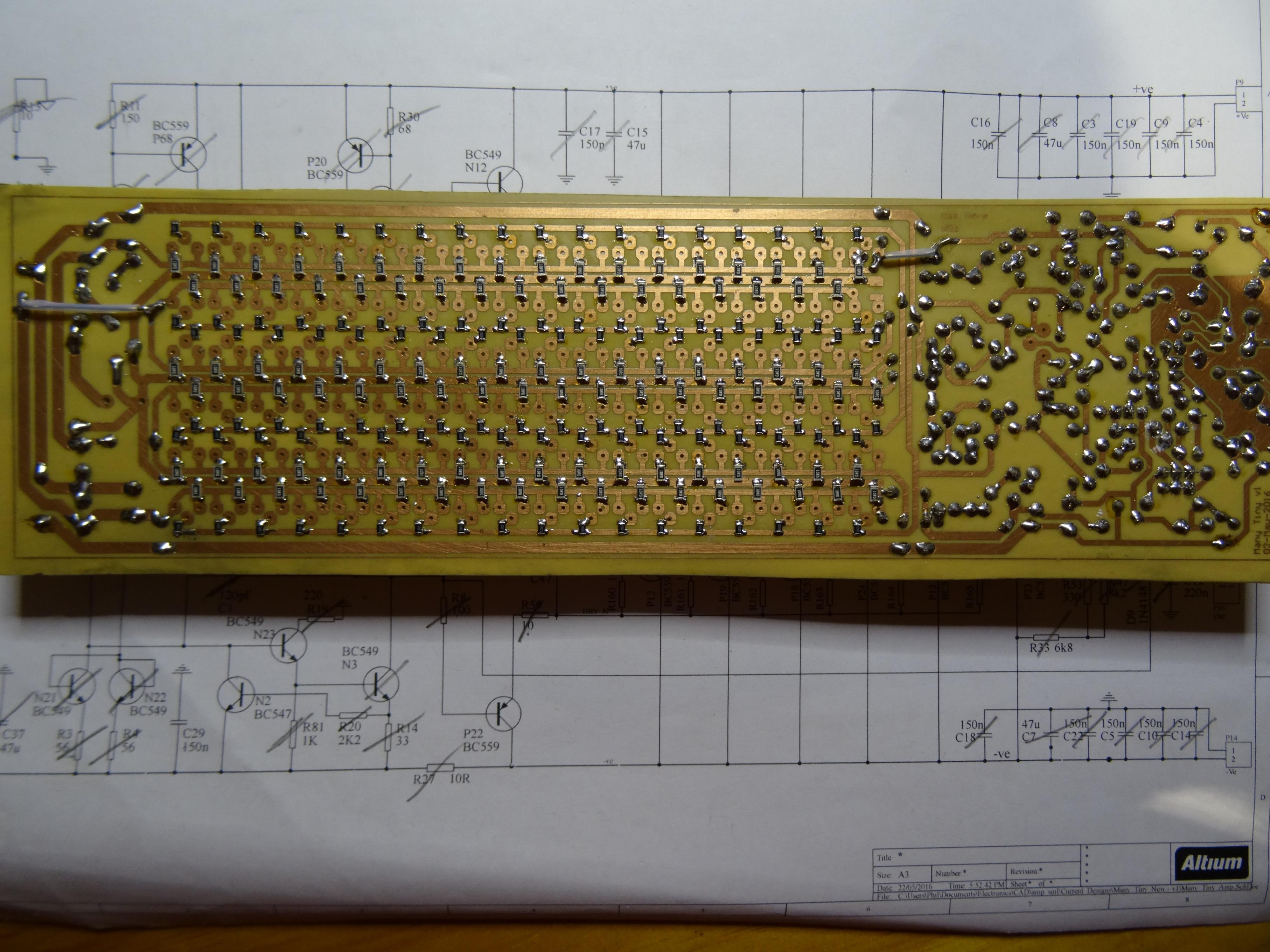
This is the beast from the back before I loaded the "output devices":

Click image for larger version

Name:	DSC05235_smaller.jpg
Views:	399
Size:	875.2 KB
ID:	1980

Note the ludicrous number of emitter and base resistors! Half way through I concluded that I was bonkers, and wasting several days hand building a complete folly.

Then again, even with the thing running, it is still a folly!


With the output devices loaded....
Attached Thumbnails
Click image for larger version

Name:	DSC05249-smaller.jpg
Views:	262
Size:	975.5 KB
ID:	1981   Click image for larger version

Name:	DSC05251-smaller.jpg
Views:	335
Size:	985.7 KB
ID:	1982  
diyAudio Member
Posted in Uncategorized
Views 787 Comments 1 googlyone is offline
Old

Adjustable Ultra Linear Linestage

Posted 27th May 2016 at 05:48 AM by ballpencil
Updated 27th May 2016 at 08:06 AM by ballpencil

This circuit is to fulfill my curiosity of hearing the sonic differences between pentode, ultra-linear and triode gain stage. As with any line stage, this circuit can also be the input part of a power amplifier. I'm considering a single ended amplifier where both the input and output stages have adjustable ultralinear percentage.. I'll show the output stage design on another post.

Anyway, i'm not sure there will be an audible difference between each mode other than gain.. but until i actually build this circuit, i can't really be sure.
Click the image to open in full size.

The idea is to use a pot to replace R5+R6. Dual 250K linear pot should do for both channel. You then adjust the screen feedback percentage by adjusting the ratio between R5 and R6. Here's how you obtain each mode:
1. Pentode mode is by making R5 = 200k and R6 = 0R. This will keep the screen grid at at fixed voltage regardless of plate swing.
2. Triode mode is...
Attached Files
File Type: asc Ultra Linear Linestage.asc (3.6 KB, 169 views)
diyAudio Member
Posted in Uncategorized
Views 492 Comments 0 ballpencil is offline
Old

Super Triode Cascode SRPP Hybrid Amplifier

Posted 26th May 2016 at 06:04 PM by ballpencil
Updated 27th May 2016 at 03:13 AM by ballpencil

Such mouthful blog title.. The idea is nothing new: to get the so-called "tube sound" from a hybrid amp. Tube sound for me comes from these two factors:
1. Triode-like linearity
2. Low to moderate damping factor
Personally, i believe number two is the main reason for tube sound. Any solid state amplifier manipulated to get a damping factor of around 1-2, instead of the typical SS amp DF that falls into the tens to hundreds, will sound like a tube amp. This is because with such low damping factor, the amp ceases to ignore the speaker impedance curve and start to become less of a voltage source and more of a current source where the bumps of speaker impedance curve will affect the amp's output.

Without further ado.. here it is:
Click the image to open in full size.

Some notes:
1. Ignore the transistor and MOSFET type. I chose them because that's what i have in LTSpice. The small signal BJT can use BC547 for...
Attached Thumbnails
Click image for larger version

Name:	Super Triode Cascode SRPP Hybrid Amplifier_2.jpg
Views:	501
Size:	63.9 KB
ID:	1978  
Attached Files
File Type: asc SuperTriode Inverted Cascode SRPP_v5.asc (4.8 KB, 185 views)
diyAudio Member
Posted in Uncategorized
Views 716 Comments 0 ballpencil is offline
Old

Disclaimer

Posted 26th May 2016 at 03:25 PM by ballpencil
Updated 26th May 2016 at 03:51 PM by ballpencil

I joined diyaudio.com on Nov 2013 and that's pretty much when i started this hobby. Maybe "restarted" is a better term as i played with diy amps, tin and soldering iron back when in junior high but somehow stopped. That being said, it should be obvious that i am just a beginner and with that:
1. There will be mistakes/misinformation. Feel free to correct me. It will be much appreciated.
2. There is no guarantee any schematic shown works in real life, unless mentioned otherwise. Basically once LTSpice shows that it works, i'm 80-90% sure it should work in real life.
3. There will be updates and revisions as i learn more, hopefully with your help!
4. There will be language barrier. English is not my first language so bear with me!

Click the image to open in full size.
diyAudio Member
Posted in Uncategorized
Views 326 Comments 0 ballpencil is offline
Old

The Graduates

Posted 18th May 2016 at 01:31 PM by G Speakers

Thought I'd give this blog thing a try.

I'm building a pair of bookshelf speakers for my wife as a gift. Don't worry, it's not one of those bowling ball gifts that's really for me. It will come with a record player and a few records of some of her favorites.

I recently found out my speaker configuration is actually a popular design by Carmody. Which makes me feel good about my choices, but also sets the bar high for me.

The baffle is a 1" thick walnut/maple butcher block look, with 1/2" baltic birch for the rest.

I made the mistake of comparing my PCD7 prediction with his. I noticed they are nothing alike. I got worried so I went back and re did my measurements to make sure I wasn't in a weird spot or getting a reflection. Even moving the mic all over I was pretty impressed with the consistency. The issue was - diffraction. Like 10dB of it. I beveled the corners, but it's still only a 6" wide baffle.
...
Attached Thumbnails
Click image for larger version

Name:	Screen Shot 2016-05-17 at 11.09.10 PM.png
Views:	124
Size:	56.3 KB
ID:	1973   Click image for larger version

Name:	neocd1.0 screenshot.jpg
Views:	113
Size:	116.2 KB
ID:	1974   Click image for larger version

Name:	w4-1720 screenshot.jpg
Views:	119
Size:	119.8 KB
ID:	1975  
Attached Files
diyAudio Member
Posted in Uncategorized
Views 569 Comments 0 G Speakers is offline
Old

And now for something completely different...

Posted 14th May 2016 at 03:48 AM by googlyone
Updated 14th May 2016 at 03:53 AM by googlyone

As a kid, which depending on my wives mood could be stated to be "right now" right through to "you have never been a kid", I once made the statement that "if it can't be done with a BC549 it is not worth doing".

this statement was made in jest at the time, and probably stolen from a similar a similar assertion about the NE555. (those of you who are < 30 years old probably haven't seen these used in real anger!)

Here I am travelling, and flying from Adelaide (Australia) to the USA. This is a long, boring flight. In a fit of boredom I set myself a challenge.

So what is the challenge? Something cool and completely different for once. Hmm. Make a power amplifier using BS549's. If you have seem my play room, amplifiers are made to scare speakers and annoy the neighbours. So this can't be a lightweight 100mW job. It must be something that actually works, and is able to make real noise.

OK, it...
Attached Thumbnails
Click image for larger version

Name:	Many_Tiny_1.jpg
Views:	515
Size:	241.8 KB
ID:	1967   Click image for larger version

Name:	Many_Tiny_2.jpg
Views:	332
Size:	256.5 KB
ID:	1968   Click image for larger version

Name:	PCB_Many_Tiny.jpg
Views:	258
Size:	235.0 KB
ID:	1969   Click image for larger version

Name:	PCB_Many_Tiny_3D.jpg
Views:	381
Size:	245.0 KB
ID:	1970  
Attached Files
diyAudio Member
Posted in Uncategorized
Views 1171 Comments 4 googlyone is offline
Old

Bboard buffer 2.0 (yet another version "2")

Posted 13th May 2016 at 08:22 AM by rjm (RJM Audio Blog)
Updated 27th May 2016 at 12:47 AM by rjm

A little bit of the sapphire headphone amp output stage, and a little bit of the LSK489 application note of all things (scroll down to Fig 10.).

Yes, this is probably the third "version 2" of this line buffer I've posted... I keep tossing it out and starting over. This variant looks pretty good: though the transistor count is a little high for such a basic function the performance is definitely there.

The main innovation re. the sapphire circuit is to replace the bias set resistors with diodes made out of the Vbe of transistors Q9 and Q10. This generates more voltage than is ideal, but can be handled by using largish values for the emitter resistors R13 and R14. Since this is a line stage buffer and not a headphone amplifier the output impedance of about 30 ohms and the limited output current swing are not critical flaws. It will drive 600 ohms at 0 dB with 0.001% THD. The whole circuit draws just 150 mW. The input impedance is a very high ~15 Mohms...
Attached Thumbnails
Click image for larger version

Name:	bboard 20.png
Views:	357
Size:	91.5 KB
ID:	1965   Click image for larger version

Name:	bboard2.1.png
Views:	221
Size:	95.8 KB
ID:	1972  
Attached Files
File Type: asc bboard buffer 20.asc (4.6 KB, 179 views)
File Type: asc bboard buffer 21.asc (4.6 KB, 169 views)
rjm's Avatar
rjm
diyAudio Member
Views 727 Comments 0 rjm is offline
Old

The Right Preamp For My First Watt F4

Posted 11th May 2016 at 05:36 PM by oltos

Hello SY,

I have one First Watt F4 amp, so I’d be running it stereo unbalanced to drive my speakers.

Since the Impasse debuted, have you or others implemented any revisions that I should know about?

My speakers are at least 94db sensitive, my room is 16 ft x 14 and my ears can’t tolerate average SPLs much beyond ~ 60db-at least not much above the lower midrange band (i.e. allowing for the Fletcher-Munson effect). My midwoofers are cut off below 70Hz, where my pair of Rythmik 12" sealed powered subs take over.

Except for the subwoofers, my speaker system is a clone of Gary Dahl’s Azurahorn 425/Radian 745 Neo Be/GPA Altec 416 system.
https://www.diyaudio.com/forums/multi-way/100392-beyond-ariel-720.html

Are there certain tube suppliers of specific brands of 6SN7 tubes, or better sounding alternatives, that you would recommend for best performance with my speakers, such as https://www.sophiaelectric.com/ ?
...
diyAudio Member
Posted in Uncategorized
Views 633 Comments 0 oltos is offline
Old

High Sample Rate PCM

Posted 2nd May 2016 at 12:13 AM by Tam Lin
Updated 12th July 2016 at 01:38 PM by Tam Lin (corrected typo)

With delta-sigma DACs pushing insane clock rates I wondered if a traditional multi-bit DAC could not do better. The fastest multi-bit I know of is the PCM1704, which has a max BCLK rate of 25 MHz. A 32-bit sample frame can run at 768 K samples per second. That is fast but not faster than DSD64.

However, with 32 DACs per channel staggered across the sample period we get 24.576 M. That is better than DSD512. For input at or below the native rate of 768K, the DACs operate in parallel. Below the native rate, inserted nulls stretch the output sample period. Above the native rate, the DACs are staggered and the data at each point is the input sample value minus the sum of the data in the other DACs. Thus, each successive sample is the delta needed to reach the next sample point. This approach has interesting repercussions: I will let you ponder them for the time being.
Attached Thumbnails
Click image for larger version

Name:	fixed.png
Views:	159
Size:	13.9 KB
ID:	1964  
Attached Files
diyAudio Member
Posted in Uncategorized
Views 693 Comments 3 Tam Lin is offline
Old

Transformers and crossfeed

Posted 15th April 2016 at 04:09 AM by abraxalito
Updated 25th April 2016 at 03:15 AM by abraxalito

Listening to headphones creates, on many recordings, an unnaturally wide soundstage. I decided to play with the idea of 'crossfeed' whereby some deliberate crosstalk is introduced between the two channels. With transformers its jolly easy to do - just create an extra winding with the right number of turns then put this winding in series with the main output of the opposite channel.

In the picture I've done this with some EP17 ferrite cores and added a DPDT changeover switch to A/B between the original and crossfed version. The crossfeed factor I've gone for is 25%. It works in practice in that there's a more natural presentation without any 'extreme' stereo effects (almost a kind of phasiness on some recordings). But sometimes I enjoy the 'all around' effect so switchable is the name of the game

Trafo winding details as follows - primary 500T of 0.1mm, two secondaries first 120T 0.21mm, second 40T 0.21mm.

Made a second one as a colleague liked...
Attached Thumbnails
Click image for larger version

Name:	xfeed.png
Views:	230
Size:	861.1 KB
ID:	1944   Click image for larger version

Name:	P60424-152341.jpg
Views:	219
Size:	294.1 KB
ID:	1959  
Attached Files
abraxalito's Avatar
diyAudio Member
Views 769 Comments 0 abraxalito is offline

New To Site? Need Help?
Copyright ©1999-2017 diyAudio