Posted 16th July 2016 at 02:04 AM byrjm (RJM Audio Blog)
Updated 20th July 2016 at 09:57 PM byrjm(corrected attenuator output impedance in attached diagram)
A [just my opinion, bro] post...
I actually had occasion to try this the other week. I had a box with a volume control followed by the bboard unity gain buffer and in preparation for replacing it with a similar buffer with voltage gain (a power-derated Sapphire 3) I removed the buffer and briefly used the box as passive preamp, i.e. just the 47k stepped attuator, with 1 m interconnects to the amp and 2 m interconnects back to the phono stage. Sure enough the system noise increased, depending on the position of the volume control, with some nasty low level buzzing interference.
Why does this happen? It's pretty simple really. Noise is usually induced as a current, and the larger the resistance (impedance) this noise current is forced to flow through to reach circuit common, the larger the noise voltage since by Ohm's Law, V=IR. Noise induced between the volume control and the amp is faced with the high impedance of the amp (47k) or the output impedance of the...
Posted 16th July 2016 at 12:54 AM byrjm (RJM Audio Blog)
Updated 16th July 2016 at 01:10 AM byrjm
When I need to pick the right capacitor for a coupling capacitor, rather than working out the time constant or 3dB cutoff I just remember the mnemonic "0.1-220" (meaning 0.1 uF and 220 kohms) and adjust the ratio up/down for the resistance I happen to be looking at: 0.22-100, 1-22, 0.47-47.
This amounts to a time constant (t=RC) of 20 ms, and 3 dB cutoff of 7 Hz. The bass attenuation at 20 Hz is half a dB.
If there are several stages the attenuation of all these filters add up, so it can be a good idea to make the capacitance about twice as large. There is rarely any advantage making it much larger still.
Excel worksheet attached. It spits out all the numbers so you don't have to guess.
* calculating the attenuation involves complex numbers. Zr=R, Zc=-i/(2 pi f RC), attenuation (high pass) = | Zr / (Zr+Zc) |. In excel you can use IMSUM, IMDIV, and IMABS to do the complex math.
Posted 13th July 2016 at 05:22 AM byballpencil Updated 13th July 2016 at 05:26 AM byballpencil
This is actually a follow up on this post: Adjustable Ultra Linear Line Stage. Here we see a slightly different variation of the first post, namely the cathode follower is now moved to the top of the small signal pentode and arriving at some kind of mu-follower circuit.
This CF will act as constant current load to the pentode and will allow us to achieve high gain. On Spice simulation, with 6K7 as shown, the open loop gain for the input stage is about 75x (15Vpp swing with 200mVpp input). This gain level is perhaps excessive so how do we tame it? As shown, the input stage is on pentode-mode as the screen grid is AC-grounded by C2 via the lower 6N8S cathode follower. We can reduce the gain by changing R16 to a 100k trimpot and connect C2 to the trimpot wiper. Adjusting the wiper, we can vary the UL feedback from 0% (full pentode mode, achieved when the wiper is at the screen grid side) to 50% feedback (achieved when...
Posted 12th July 2016 at 01:24 PM byTam Lin Updated 17th July 2016 at 07:03 PM byTam Lin(typo)
Theory tells us that each time the number of DAC chips is doubled the SNR increases by 3 dB. With 32 chips per channel, we should see a 15 dB increase. That is very good, but we can do better because there is no reason the paralleled DAC chips have to receive identical input data.
In essence, we have a 29-bit DAC for sample rates at or below 768K. For each 24-bit input sample value, we can provide a 29-bit value that produces an output current that is closest to the ideal. Accessing a 16MB look-up table 768K times per second is trivial for a modern 64-bit microprocessor. The table data comes from a one-time calibration procedure that analyses the DAC’s measured output performance for each possible input.
Above 768K, we are dealing with a delta that is obtained by scaling the difference between consecutive samples. Below 11.2896M, two or more chips are paralleled and a table lookup is used to improve accuracy.
Posted 7th July 2016 at 11:58 PM byabraxalito Updated 8th July 2016 at 12:01 AM byabraxalito
I've not posted for a few months here as I've been involved in moving apartment which was quite a major project given the quantities of parts and assemblies I've accumulated. Even though I've been in my new place for over two weeks now, very little has been unpacked so far, but I have just yesterday rebooted my desktop active XO/amp system which had been quite literally assembled on my desktop with no casework whatsoever Its still without casework and survived the move with only a few wires falling off but now 'installed' in a drawer (pic attached). Its being fed from my 'Domino' balanced TDA1387 DAC and Taobao TFcard player and delivering bags of emotional satisfaction through stand mounted '3Nod' two-ways.
The amps are all LM4766 bridged running from 60V total but with heroic measures to keep supply noise under control, the central PSU has a CLC configuration and ferrite input transformers are used for coupling between AXO and amps. Output transformers (ferrite for...
Posted 26th June 2016 at 08:12 AM byrjm (RJM Audio Blog)
Updated 18th July 2016 at 03:42 AM byrjm
Asus Xonar Essence STX, Audacity 2.1.2, VLC, Windows 10 [and DigiOnSound6 Express for 24 bit recording]
Purpose
To confirm the calibration of the sound card input and output gain. Also, to determine the relationship between the signal voltage, the recorded signal amplitude displayed in Audacity, and the signal peak and noise baseline levels in the FFT spectra.
Summary
* Setting the volume slider of the device output to 100 gives 1 V rms output for an amplitude 0.5 sine wave.
* Setting the volume slider of the device recording line input to 100 gives records a 1 V rms tone as an amplitude 0.5 sine wave, which is displayed in the frequency spectrum (FFT) as peak of magnitude 0 dB in Audacity when both channels are averaged.
* volume setting 100 needed for unity gain loopback.
* 0.5 amplitude sine wave = 0 dB FFT = 1 V rms.
* noise baseline in averaged stereo FFT is 3 dB lower than single channel measurement....
C4 was a 5mm lead spacing Wima MKP but the board spacing is only 2.5mm. The part is changed to Wima MKS with 2.5mm lead spacing.
R22,23 was incorrectly given as 47.5k, it should have been 4.7k and has been since updated to 10k. This is not a critical value, the circuit will work with any of the resistances.
Posted 17th June 2016 at 01:44 PM byrjm (RJM Audio Blog)
Updated 20th December 2016 at 12:01 PM byrjm
I'm not totally sure this would work as advertised, but I can't see any obvious reason why it would not...
It's pretty much the same circuit as I used in the CrystalFET, which started out in a previous blog post in the Voltage Regulators for Line Level Audio series, but here I've replaced the MOSFETs with bipolars. It is shown configured to deliver 20 mA @ 12 V, split supply. Enough to power an op amp phono stage for example, or a preamp, or the voltage gain stage of a headphone amplifier.
Posted 4th June 2016 at 04:42 AM bygooglyone Updated 4th June 2016 at 05:18 AM bygooglyone
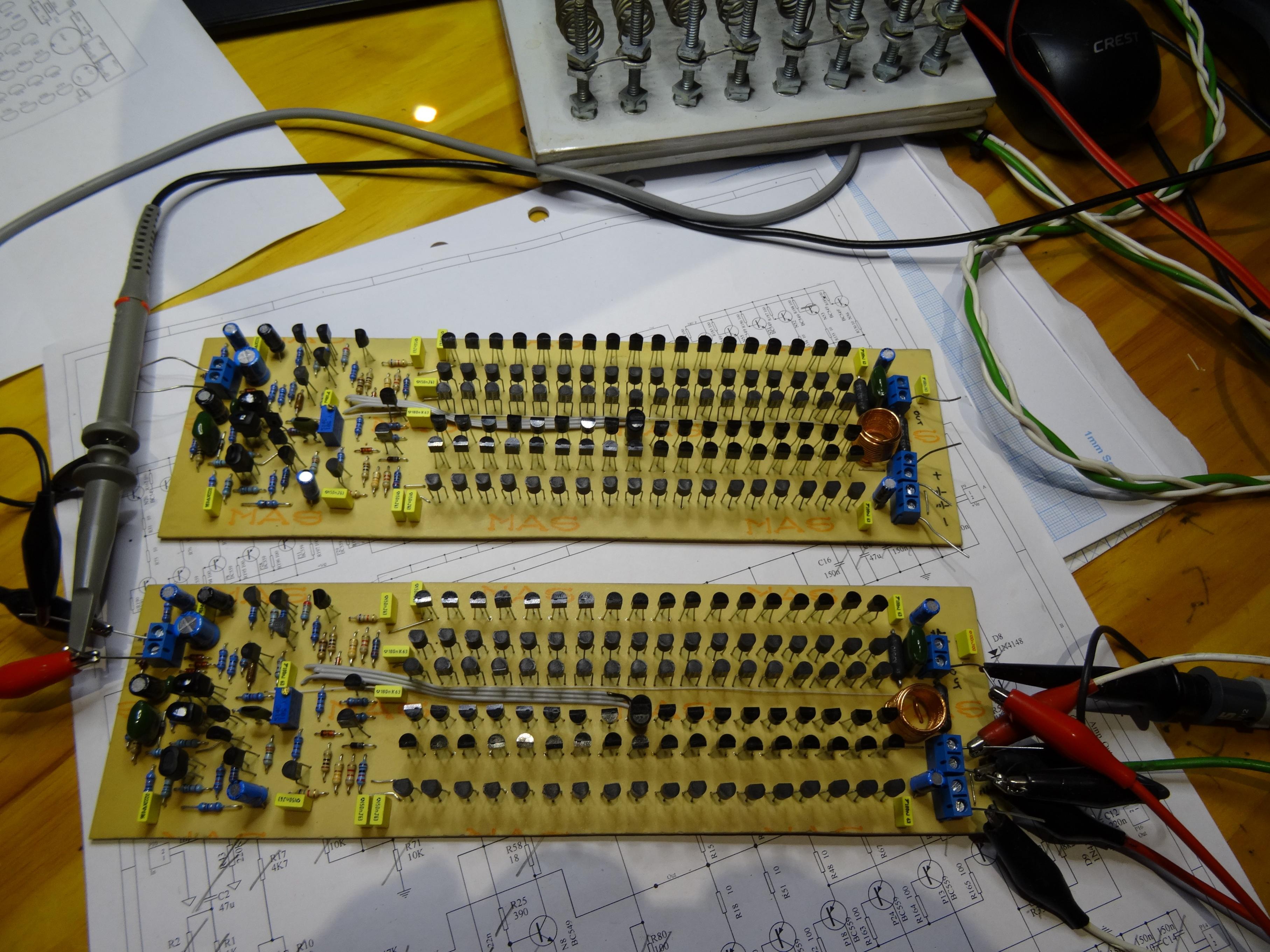
I finally got around to rolling out the distortion test set and the Amplifier of 100 Transistors to measure its performance.
I would like to say that I don't care - and that the whole thing is an engineering abortion. A complicated joke, and that the measurements don''t matter. The fact that I am making the measurement would however show me to be a liar - as if I didn't care, then why did I do this?
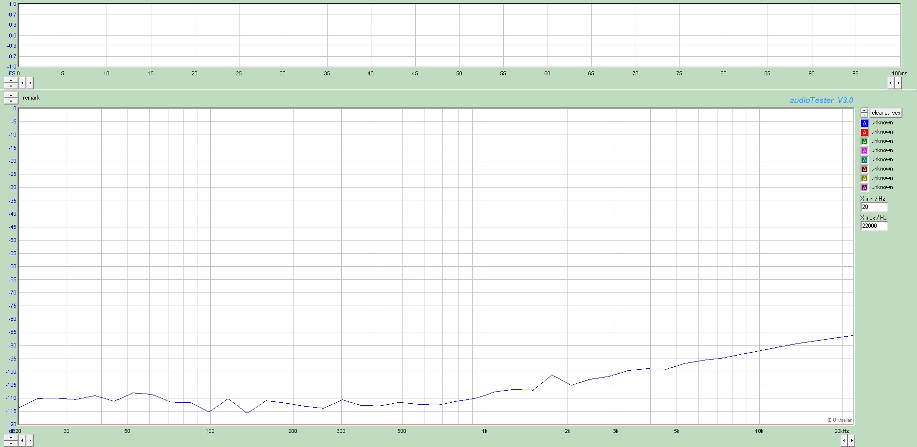
Anyway, with low distortion measurements, getting your head around the baseline of your test gear is key. With all gains / levels being equal, here is the loop-back distortion of the test system:
Which is fine, rolls along at about 0.0003% across the band.
Then I ran a sweep of the Amplifier of 100 Transistors with NO load at 3dB below clipping:
OK, this is saying the amplifier distortion raises it's head above the noise floor at 1KHz and is...
And then there were two! A lot easier simply loading just the "output devices" and testing.
The second one initially looked super stable, but after I got it quite warm by running an almost clipping sinewave into a 4 Ohm load, I did find just a tough of oscillation on negative excursions.
The first amp had envelopes of oscillation at 3MHz. The frequency of the second amps oscillation was 13MHz.
In the end removing the capcitor between the bases of the output devices (what was it there for anyway?) tidied things up.
These Amplifiers of 100 Transistors seem to breed!


 Its still without casework and survived the move with only a few wires falling off but now 'installed' in a drawer (pic attached). Its being fed from my 'Domino' balanced TDA1387 DAC and Taobao TFcard player and delivering bags of emotional satisfaction through stand mounted '3Nod' two-ways.