AX-14 aka kelvin v2? hum, i wonder why? i should try to ltspice it up and see how it measures.
I was going through some of the threads, to figure out what is what 🙂
Terry did you ever see/build the complementary jfet or bjt pre-amp types?
sf3.1, sb3.1?
also, what tests are you running on these amps?
thx rick
Apex AX14 as an IPS attached to Slewmaster EF3 5P OPS.
No, I didn't try the other pre-amps. I think Juan Vargas is doing a layout for at least one of them. If he post one I will try it.
The only tests I run are sine and square waves through my scope. 1khz-100khz. And of course A/B listening. Nothing very scientific,
Last edited:
You must build AX11! 😀
OK here's a start.
Attachments


Yes,
There are tests/measurements that show that the distortion caused by using Mylar (polysomething) is greater than when using MKP (polysomethingelse).
But these "tests" apply when the passband is filtered by the capacitor value.
Coupling capacitors do not filter the passband. They should be selected to PASS the wanted signal and roll-off only the unwanted signal.
In this style of operation there is no signal voltage across the coupling capacitor. When there is no signal voltage, there can be no added distortion to the passing signal. D.Self does a revealing test of MKP vs Mylar in one of his books. Here it was a filter capacitor that increased the distortion and he correctly reports WHAT HE TESTED !
Yes, MKT (of all types) can be used as very effective coupling capacitors that will not interfere with the wanted signal, if the correct value is chosen.
You gain nothing (in my opinion) by adopting MKP, FKP, and exotic concoctions as coupling capacitors.
Read the test reports and see for yourself what they are actually reporting.
The school seems to be out arguing/agreeing what Dielectric Absorption (DA) does to "Sound Quality"
BTW,
tests that report the results of using "ears" as measuring instruments, fail to mention:- the change in shape and change in wire lengths and change in signal loop areas and change in .....etc, as possible causes for apparent differences in "sound quality".
Maybe imagination could/should be added to that last list.
Last edited:
OK here's a start.
Terry you gonna love it 😀 my friends here in Puerto Rico said they never heard music as sweet and nice specially with Salsa music 😛 with the AX-11
Regards
Juan
I don't have MPSA13. Can I use MPSA29 instead?
Yes, 2N5551 can be use but with 1k5 instead 4k7 in bias servo circuit.
Last edited:
OK, I finished the AX11.
I have a few questions.
Bias is low. 2mv across the pair of R22 emitter resistors.
Gain is low. 1Vac input = 15Vac output.
Sine and square waves look good and music sounds good aside from the low gain.
I made substitutions based on what I had on hand so I am sure some of this is to blame.
I changed BC639/640 for MPSA06/56. (twisted legs for pinout)
MPSA13 changed to MPSA29
BD249/250 changed to MJL3281/1302
Suggestions?
Blessings Terry
lots of incarnations of AX-11, from one sch I see
R7 is 22k and R8 is 2.2K
gain is 1+(R7/R8) = 11 or 21dB, seems correct
R7 is 22k and R8 is 2.2K
gain is 1+(R7/R8) = 11 or 21dB, seems correct
Yes, correct but pretty low without a pre-amp.
For the bias I suppose I should attach a trimmer to the 4k7 and see what I need there.
For the bias I suppose I should attach a trimmer to the 4k7 and see what I need there.
Last edited:
Yes, correct but pretty low without a pre-amp.
For the bias I suppose I should attach a trimmer to the 4k7 and see what I need there.
Replace R8 with 680R instead 2k2 to increase gain. Instead 4k7 use 1k trimmer in series with 3k3 resistor and set 20-30mA bias.
Regards
Replace R8 with 680R instead 2k2 to increase gain. Instead 4k7 use 1k trimmer in series with 3k3 resistor and set 20-30mA bias.
Regards
Thanks Mile,
I installed the 680R. What I did with the bias was to parallel a 100k pot with the 4K7 and adjusted until I had 12mv across the emitters. Then measured the resistance at about 3k9 so I pulled the 4k7 and in stalled 3k9 in both boards. Once warmed up both boards are holding between 12-15mV which is around 30mA per. Gain is greatly improved. The amp now clips at 25V with .8V input. It clips soft. Squares look great in the audio range, especially in lower range.
I A/B'ed it against a Symasym and it is indistinguishable. Very nice!
Attachments
-
 AX11 clipping.jpg669.4 KB · Views: 192
 -
 50KHZ.jpg525.8 KB · Views: 193
 -
 20khz.jpg555.6 KB · Views: 365
 -
 10khz 10vac.jpg583.1 KB · Views: 210
 -
 1khz.jpg573.4 KB · Views: 1,108
 -
 500hz.jpg572.2 KB · Views: 1,152
 -
 200hz.jpg544.8 KB · Views: 1,275
 -
 100hz.jpg537.9 KB · Views: 1,389
 -
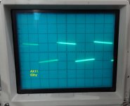 50hz.jpg572.1 KB · Views: 1,565
With less than 330pF compensation you could have even better square wave response, but for a simple amp this is very good. I used 100pF without problems and instead of 680R I used 1k (gain of 23). I am building my second pair of AX11 boards at the moment.
Still4, your sqw test signals have a slow slope.
What input filter have you fitted?
This is the asbuilt.
Attachments


With less than 330pF compensation you could have even better square wave response, but for a simple amp this is very good. I used 100pF without problems and instead of 680R I used 1k (gain of 23). I am building my second pair of AX11 boards at the moment.
as ivan said,you would get better results with 100p or a bit more instead 330p compensations.
This is the asbuilt.
Use 470uF instead 100uF in feedback circuit for better low frequency square waves, 10uF on input can be shorted for test.
Last edited:
- Home
- Amplifiers
- Solid State
- Studio Reference Amplifier