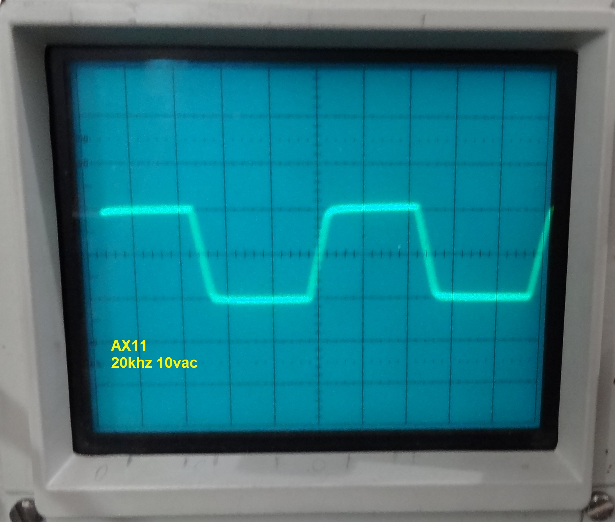
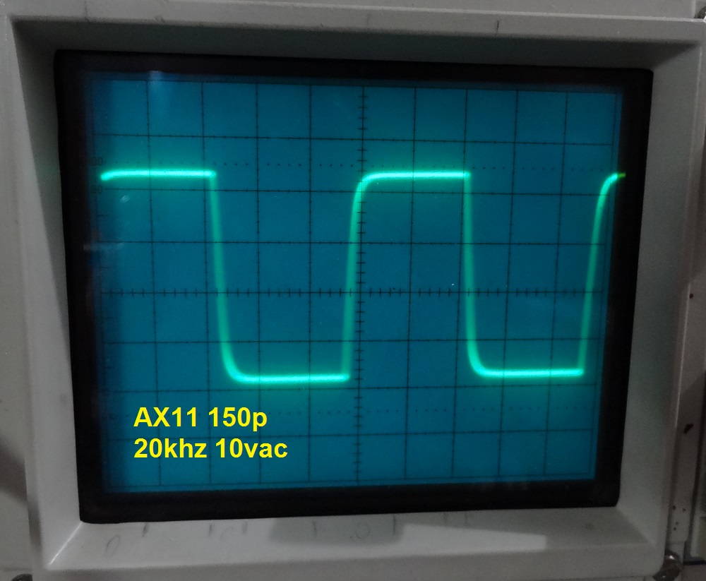
OK,couldn't find my bag of 100p so I just replaced with 150p. I also changed the feedback to 470uF. Here are the new squares.
Attachments
-
 50hz 150p.jpg159.1 KB · Views: 1,658
 -
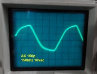 150khz 150p.jpg153.5 KB · Views: 214
 -
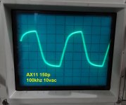 100khz 150p.jpg192 KB · Views: 230
 -
 50khz 150p.jpg177.5 KB · Views: 232
 -
 20khz 150p.jpg177.2 KB · Views: 321
 -
 10khz 150p.jpg168 KB · Views: 1,420
 -
 1khz 150p.jpg172.2 KB · Views: 1,470
 -
 200hz 150p.jpg173.2 KB · Views: 1,518
 -
 100hz 150p.jpg170.1 KB · Views: 1,590
http://www.diyaudio.com/forums/atta...29591727-studio-reference-amplifier-20khz.jpg
http://www.diyaudio.com/forums/atta...316-studio-reference-amplifier-20khz-150p.jpg
this is much much better - only you haven´t adjusted "zero-point" on your osciloscope in second measurement , i´d say...
now i want to replace 330p to 100p in my AX11... 🙂
http://www.diyaudio.com/forums/atta...316-studio-reference-amplifier-20khz-150p.jpg
this is much much better - only you haven´t adjusted "zero-point" on your osciloscope in second measurement , i´d say...
now i want to replace 330p to 100p in my AX11... 🙂
You're right. I was lazy and didn't center before taking the pictures. I also kicked the volts/div up a notch so the wave was bigger. Definitely better in the higher frequencies. The bigger cap in the NFB helped the lows too. I don't really hear any improvement but I can see it on the scope.
Blessings, Terry
Blessings, Terry
it´s all right,it often happen´s to me too 🙂 i said just to "delete" any doubts that an amplifier did that...
my AX11 even today works with 330pF and even with them i don´t have any complains how it sounds. i will surely try it with 100-150pF just when i get some time and right capacitors! 🙂
my AX11 even today works with 330pF and even with them i don´t have any complains how it sounds. i will surely try it with 100-150pF just when i get some time and right capacitors! 🙂
I have had it playing all morning. This amp has surprisingly good bass for such a simple circuit. This one's a keeper.
it is not necessary to use that large IRFP,you can use smaller one but also increase sors resistors value.
with H version the idea was to have A-class first watt of power to a loadspeaker with about 300mA (or more) of bias.
What about IRF610/IRF9610?
Please keep us to date about any tests/improvements.

What about IRF610/IRF9610?
Please keep us to date about any tests/improvements.
There is FB200
http://www.diyaudio.com/forums/solid-state/162081-dc-servo-mosfet-amplifier-38.html
I have had it playing all morning. This amp has surprisingly good bass for such a simple circuit. This one's a keeper.
"cheap trick" amplifier, just it's no trick with it! 🙂
That's ~0.7us.This is the asbuilt.
That has an enormous effect on the test signal. Enough to ruin any sensible results.
A 10kHz sqw goes out way past 100kHz with a very strong content and beyond 1MHz with some content.
You need to drop the input resistor by a factor of ten or increase the RF capacitor by a factor of ten. Don't do both that would probably be too fast.
Then you will see if the amp can tolerate the faster slopes of the test signal.
Once you have examined the amp's tolerance to a fast signal, you put back the original RF filter values so that RF is actually attenuated and ALL the Audio is passed through.
Last edited:

Hi Mr Mile, can I use PSU10 with protect
Like this
Yes you can.
Regards
Thank's Mr Mile.
I'll use it for stereo AX-11
Any change with 45V AC 20A?
Regards
Use 12V zeners instead 20V
Regards
SR-100
Hi Sir Mile here's my SR-100
What is the max rail voltage for SR-100
I have 33-0-33 volt ac toroid 500VA
Can I use this for SR-100


Hi Sir Mile here's my SR-100
What is the max rail voltage for SR-100
I have 33-0-33 volt ac toroid 500VA
Can I use this for SR-100
Hi Sir Mile here's my SR-100
What is the max rail voltage for SR-100
I have 33-0-33 volt ac toroid 500VA
Can I use this for SR-100
Nice work, 2x33vac willbe ok
Regards


SR75 idea
Hi, Mile 🙂
There are some mistakes I made in the schematics SR75-STD03 amplifier we discussed in our local caffe`:
-T7, T8 and T9 (BD139 V_be multi) must be mounted on separated DRIVER Heatsink. (NOT T14!!! ...like in the Schematics notes)
Driver bias is adjustable with multiturn trimmer P1, so that we read cca 3,9 - 4,0VDC across R6 (150R, 26-27mADC).
V_be is only for driver bias idle and driver thermal compensation.
Driver Heatsink must be grounded for minimization of RF interference....don`t forget BJTs mica isolations!
Drivers runs also in class A (like input LPT and VAS) @30mA, from STD03 DS we aspect worst scenario with h_fe 400@10A I_c,
so we have good "current stock" that also drivers never live class A region.
For R8 go with 10R resistor, so we can read cca 40mVDC across R8 for verifying Tracking diodes idle current!
This idle current must be limited to Max 10mADC, but most suitable Track current is around 2 - 5mADC (see DS)!
Setting STD03 pair for cca 65mADC bias-idle current with multiturn trimmer P3 that we can read 28-29mVDC across both emitter resistors (2x0R22, 65mADC).
P2 multiturn trimmer is for output offset adjustment.
T10 and T11 (VAS) also runs hot with aproxim. 0,7W each (cca 50VDC, 13mA), so they need little heatsink for good term. dissipation
Spec:
PS: +/-45VDC to +/-55VDC for one pair STD03
P_out max : 75Wrms / 8R0 (PS= +/-50VDC)
Input sens: cca max 950mVrms
Input impedance: cca 23K ohm
Ao = 27dB
BW : (-1dB) 2,2Hz - 171KHz
Input voltage noise dens. : 5,5nV/sqrt(Hz)
SN : 108dB@1Khz
THD+N : 0,003% @ 10Wrms/8R0
If we plans to make output stage with multi pairs of STD03 to achieve more output power (150, 200WRMS...),
they must be closely matched (pairs) and then we go with step-by-step adjusting pair per pair idle/bias currents
in little alternating steps to obtain bias current 65mADC per output pair,
also drivers needs more current (+30mADC per output pair) , bigger heatsink, higher PS...
There will be some interactions in this adjust steps and also we need to check "in-between" to re-adjust the driver+Trak bias to 26-27mADC and 4mADC respectively!
Regards
- Home
- Amplifiers
- Solid State
- Studio Reference Amplifier