which rule states that capitals cannot be used to emphasis the point?
Either that rule does not apply to you or not visible on your desktop
") . I sincerely don't know. Its applicable to me.
. I sincerely don't know. Its applicable to me.http://www.diyaudio.com/forums/site-announcements/167561-diyaudio-rules.html
Last edited:
Are you interpreting that as meaning no one is ever allowed to use any capitals?16. Posting in CAPITAL letters.
And rule 16 is not listed in the whole "rules" section I quoted in post 8280
http://helpdesk.diyaudio.com/article/15/the-rules
yes.. you could have used simple plain text. you would have perfectly conveyed the message to me to modify the silk.Are you interpreting that as meaning no one is ever allowed to use any capitals?
And rule 16 is not listed in the whole "rules" section I quoted in post 8280
The rules | diyAudio Helpdesk
So?... its there on the forum main page under a separate section named 'Rules'
Last edited:
Are you interpreting that as meaning no one is ever allowed to use any capitals?
Then you will be one of a very few Members that interpret that Rule as meaning "never use any capitals".yes.. you could have used simple plain text. you would have perfectly conveyed the message to me to modify the silk.
So?
Then you will be one of a very few Members that interpret that Rule as meaning "never use any capitals".
So be it. and you are one of the very very few members that think they can violate rules and think its perfectly alright, without any thought on how the person who reads it actually interprets, i might add.
So be it. and you are one of the very very few members that think they can violate rules and think its perfectly alright, without any thought on how the person who reads it actually interprets, i might add.
Prasi, please pretend he does not exist
Although, sometime he is right but do not argue. It is useless
Mr Mile and others can i substitute the 47R 25watts resistor in the soft start with NTC of appropriate amps as shown in the attachments
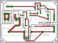
what you are planning to make here is a dangerous ckt with mains voltages. please read more on how to make layout for mains voltage or follow some tested layout.
reg
Prasi
What am I missing? What do you consider to be dangerous about this layout?
the clearances between the edge of PCB and holes from copper is less;+live and neutral very close i think. A good guideline on proper PCB design is given in http://www.infineon.com/dgdl/Infine...s.pdf?fileId=db3a30433d1d0bbe013d20e0cbf017fe
I dont know if the above link works , but there are some online calculators that show the clearances and also precautions to be taken when dealing with mains ckts and min clearances as per standards.
Last edited:
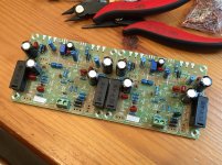
AX11 Bimo progress. Everything but transistors and some terminals and caps. 70um thick copper is nice to work on. So much more durable. Build is pretty easy. I can't believe I don't have a 220R 0.5w or 180R. I substituted 200R for 180R. Also just using 2W 0.22R emitter resistors. I have 5w white cement ones but their pins are a bit too thick for the supplied holes. I think I will play and see how hot it gets. Can swap out later if a problem. My experience says that a 0.22R here won't get that hot and 2W is fine.
Attachments
Last edited:
what you are planning to make here is a dangerous ckt with mains voltages. please read more on how to make layout for mains voltage or follow some tested layout.
reg
Prasi
Hi prasi, thanks
I am not trying any new layout just copied willis layout of apex softstart which is attached as PDF,just added two legs for NTC parallel to 25w resistor and want to know it's ok , others will correct as per advice
AX11 Bimo Mod First Sound
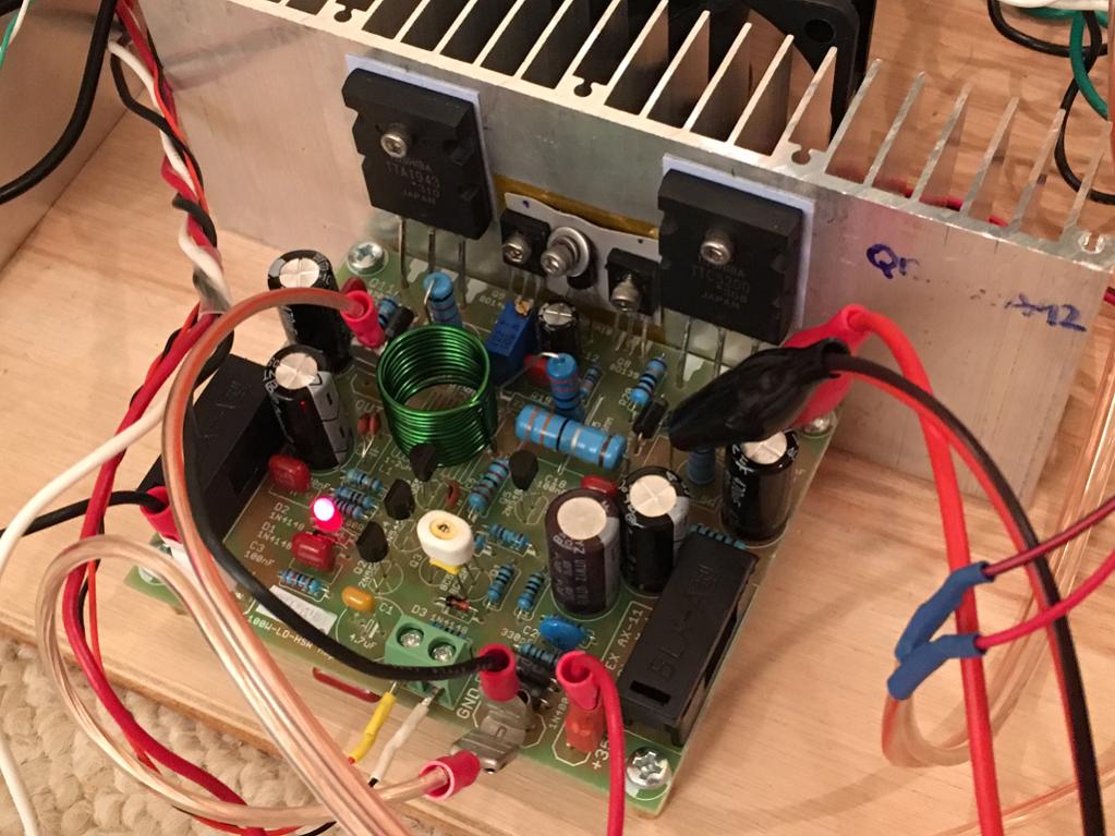
I couldn't wait for the NJW's to arrive. I had some 2SA1943's and 2SC5200's lying around (genuine Toshiba). So I proceeded to install the outputs. I swapped one of the 1N4148's (D2) with a red LED for power on indication. It is singing now but the bias adjustment on the Vbe multiplier seems to be off. I can adjust bias current but it bottoms out at 486mA (as measured with probe at R22 - the 0.22ohm, emitter resistor). So it is sort of running class A with lots of heat output so I added a fan. I am using BC546C as the temperature compensation Vbe multiplier. What values of resistors do I need to change out to get the range to go lower?
Currently running 35v rails. Bias is rock steady at - so the BC546 clamped to heatsink seems to be working. DC offset is -23mV (even though I matched the Hfs of the input BC550's).
Attachments

Last edited:
I couldn't wait for the NJW's to arrive. I had some 2SA1943's and 2SC5200's lying around (genuine Toshiba). So I proceeded to install the outputs. I swapped one of the 1N4148's (D2) with a red LED for power on indication. It is singing now but the bias adjustment on the Vbe multiplier seems to be off. I can adjust bias current but it bottoms out at 486mA (as measured with probe at R22 - the 0.22ohm, emitter resistor). So it is sort of running class A with lots of heat output so I added a fan. I am using BC546C as the temperature compensation Vbe multiplier. What values of resistors do I need to change out to get the range to go lower?
Currently running 35v rails. Bias is rock steady at - so the BC546 clamped to heatsink seems to be working. DC offset is -23mV (even though I matched the Hfs of the input BC550's).
X,
the following was advised regarding this amp by Bimo and Andrew T.
Use Either of
1. D1+D2 (default)
2. Led+D2 (R4=TBD, R6=TBD)
3. Led+Jumper (R4=10k, R6=330)
So its better to use D1+ D2 or Led +jumper with R4/R6 changed.
reg
Prasi
Last edited:
Change R14, use 1k5 instead 1kI am using BC546C as the temperature compensation Vbe multiplier. What values of resistors do I need to change out to get the range to go lower?
Doesn't R14 and R13 control the bias adjustment range as those are the upper and lower resistors in the Vbe multiplier? R4 and R6 control the CSS current - which, I am not sure if that affects the bias current.
ok, i just saw the red led being used and i remembered the advice. may be b Mr. Mile or Bimo can advice on suitable values for R13/14 for the BC546.
Last edited:
X,
the following was advised regarding this amp by Bimo and Andrew T.
Use Either of
1. D1+D2 (default)
2. Led+D2 (R4=TBD, R6=TBD)
3. Led+Jumper (R4=10k, R6=330)
So its better to use D1+ D2 or Led +jumper with R4/R6 changed.
reg
Prasi
1. D1+D2 (default)
2. Led+D2 (R4=10k, R6=470)
3. Led+Jumper (R4=10k, R6=330)
- Home
- Amplifiers
- Solid State
- 100W Ultimate Fidelity Amplifier