AX11 most popular amp")
Hello apex sir
http://www.diyaudio.com/forums/atta...4-100w-ultimate-fidelity-amplifier-ax11-2.jpg
How to start testing this AX-11(post #1980) before attach to speaker.Please can you give step by step instruction.
FH9/FH11 adapted to each other (I)
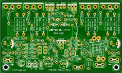
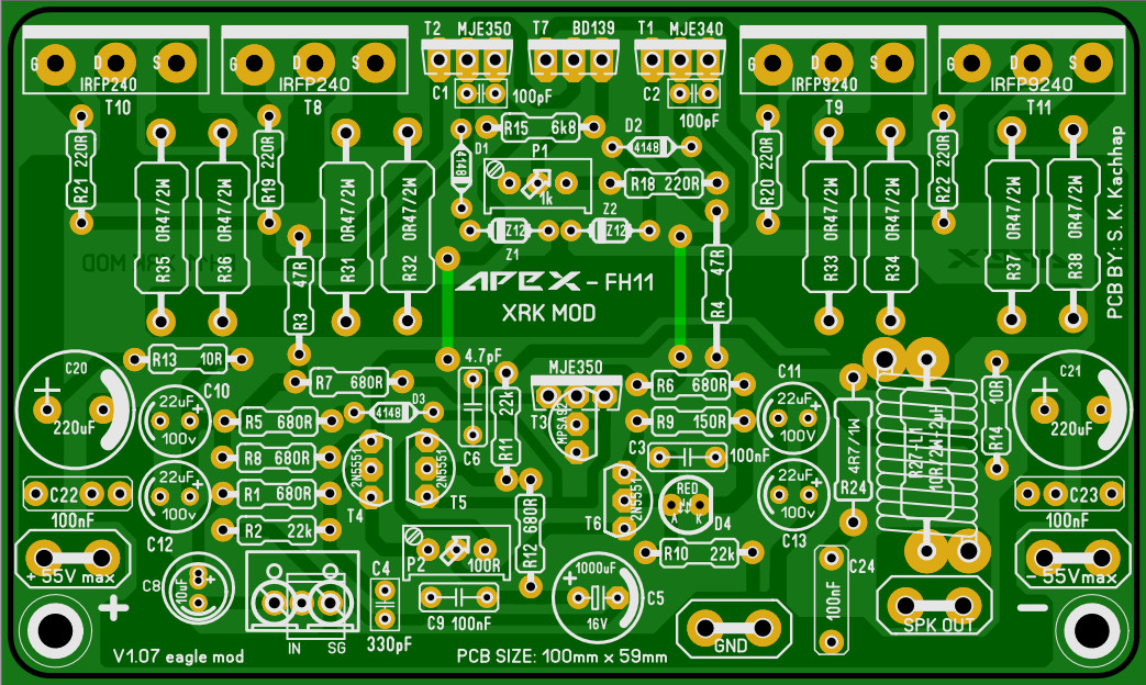
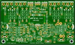
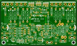
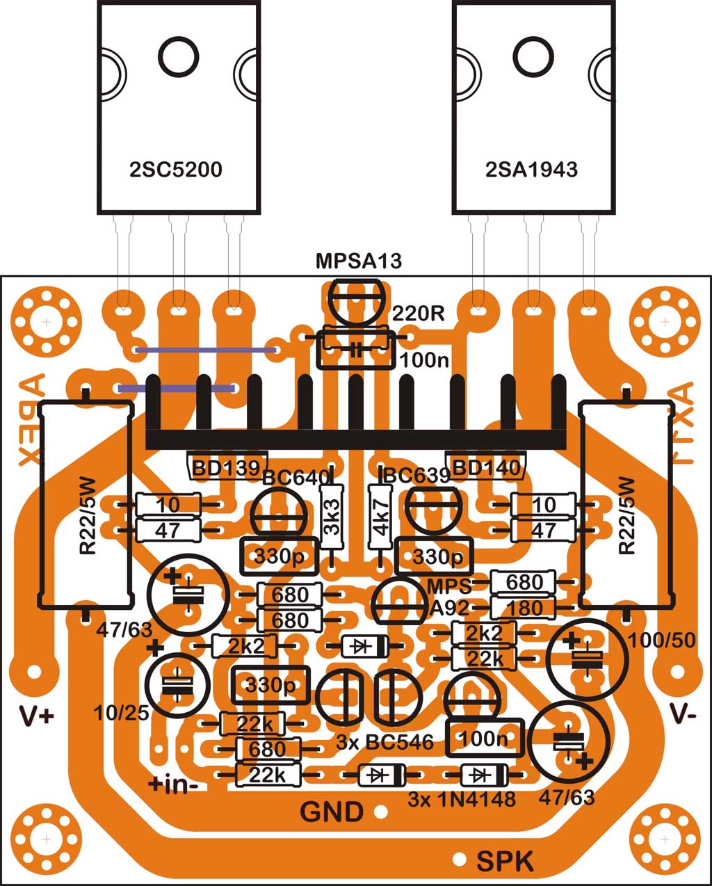
Here are now the Gerbers and the BOM (V1.0.7) for FH11
Most of the parts are the same for these 2 amps. So the idea was, to choose same part designators (R1, C1, etc) to same parts in layout as well as in the schematics and the BoMs.
Here are now the Gerbers and the BOM (V1.0.7) for FH11
Attachments
Hello apex sir
http://www.diyaudio.com/forums/atta...4-100w-ultimate-fidelity-amplifier-ax11-2.jpg
How to start testing this AX-11(post #1980) before attach to speaker.Please can you give step by step instruction.
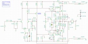
Like all amps here, use either a light bulb mains tester or 10R safety power resistors between the PSU and amp on each rail. Ground the inputs. Use DMM to monitor current on safety resistor. Observe voltage when applying power for first time. If more than 10v (more than 1amp across resistor) immediately disconnect power and debug. If less, circa 2-3v adjust bias trimpot to desired level. Then check DC offset. If all looks good, disconnect power, remove safety resistors, connect speakers, connect audio input to source and enjoy your amp.
We've tried to create a Uniform Mounting Standard, so PCB's will bolt right into the chassis' at the diyAudio Store and any other chassis maker who wants to use the standard. All PCB's in the store bolt right in, and we were hoping other designs would do the same...
Universal Mounting Specification – diyAudio Store
UMS 40mm Heatsinks – diyAudio Store
Deluxe 4U Steel – diyAudio Store
There's no requirement to do this of course, but it makes it more likely amps will be built!
Universal Mounting Specification – diyAudio Store
UMS 40mm Heatsinks – diyAudio Store
Deluxe 4U Steel – diyAudio Store
There's no requirement to do this of course, but it makes it more likely amps will be built!
Last edited:
Like all amps here, use either a light bulb mains tester or 10R safety power resistors between the PSU and amp on each rail. Ground the inputs. Use DMM to monitor current on safety resistor. Observe voltage when applying power for first time. If more than 10v (more than 1amp across resistor) immediately disconnect power and debug. If less, circa 2-3v adjust bias trimpot to desired level. Then check DC offset. If all looks good, disconnect power, remove safety resistors, connect speakers, connect audio input to source and enjoy your amp.
Hello Xrk971
Thanks for replay.But how to ground the input meaning is it I have to attach input ground to power ground and stay open input signal.what is offset volt to set.how much volt I have to set acros 10R resister.
As suggested track, also PCB size was now reduced to 60X70mm.
Regards,
Sure...
Regards,
Hello wiljj78
What is replacement of transistor BD249c/250c.and other transistor in my area it is hard to find BD249/250.Can i use 2sc5200/2sa1943 and can you suggest any BC replacment for mpsa92/13. What other changes i have to make in circuit. I have 35+/- supply.please help.
hello ahmadfaymy AX-11, nice sound....

Which transistor you used in your AX-11 in post #2152. photo is not clear. can you post Bill of materials in details.
Eaglemaster,
Thanks for the nice layout. I really want to build this but my to-build list is already too long. Looks nice though to give flexibility in design and great mod of Sonal's excellent starting layout.
It's such a beautiful board I may order some just to have for a rainy day.
Thanks for the nice layout. I really want to build this but my to-build list is already too long. Looks nice though to give flexibility in design and great mod of Sonal's excellent starting layout.
It's such a beautiful board I may order some just to have for a rainy day.
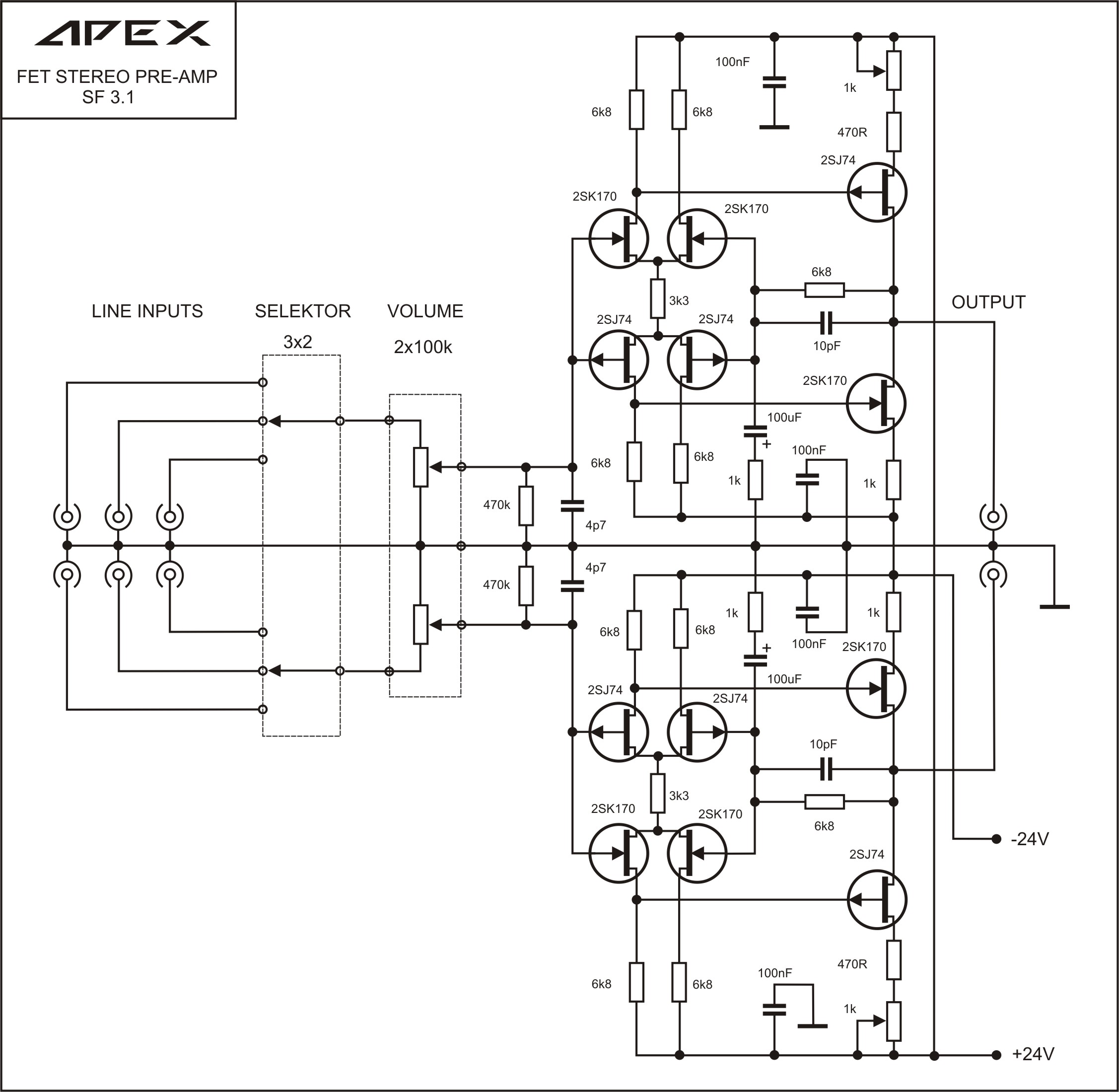
Preamp circuit SB3.1 is simplified version of my preamp from 1990.
Is there a PCB layout for this somewhere?

Eaglemaster,
Thanks for the nice layout. I really want to build this but my to-build list is already too long. Looks nice though to give flexibility in design and great mod of Sonal's excellent starting layout.
It's such a beautiful board I may order some just to have for a rainy day.
Many thanks, xrk971.
Though I spent a lot of time I conciously tried to keep the changes in the design of the amp and the PCB as low as possible for some good reasons. My experience in amps is far away from yours and my experience in PCB design for amps is even farer away from Sonal's.
Nevertheless I wanted to be able to built both amps on the same PCB (I ordered in the meantime). My space I have for the PCB allows 100mm, so this is no restriction for me! Only for those who have similar intentions and low restriction too, I published the results!
Here are now the Gerbers and the BOM (V1.0.7) for FH11
Hi Eaglemaster,
Very beautiful layout indeed. If I understand correctly, the idea is to use same PCB for both amps? In that case, would it be possible to mark additional components for second amp with a dot mark?
reg
Prasi
FH11 V1.07 Some more information on the silk screen!
I marked those parts which can be omitted for FH9 with a full dot and those parts, which have different values with a ring.
Find attached the changed silk screen Gerber file.
A great idea, Prasi!Hi Eaglemaster,
Very beautiful layout indeed. If I understand correctly, the idea is to use same PCB for both amps? In that case, would it be possible to mark additional components for second amp with a dot mark?
reg
Prasi
I marked those parts which can be omitted for FH9 with a full dot and those parts, which have different values with a ring.
Find attached the changed silk screen Gerber file.
Attachments
Thanks for updating that Eaglemaster. Are we pretty satisfied that this layout is now error free? I want to order some boards. I think this is perhaps one of the most useful amps as it can be configured as either single or double outputs. Sounds great. Easy to build. Sinple to setup. Make one of these and give as gifts to friends and they will be amazed at the sound compared to most stuff they hear.
This amp is a perfect match for the $25 Abletec 53v SMPS.
http://m.ebay.com/itm/Abletec-900-W...fier-power-supply-53V-DC-UL-cUL-/251804683031
This amp is a perfect match for the $25 Abletec 53v SMPS.
http://m.ebay.com/itm/Abletec-900-W...fier-power-supply-53V-DC-UL-cUL-/251804683031
Last edited:
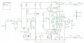
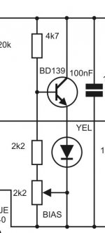
If you're going to have PCBs professionally made, I would also add a LED in series with VBE multiplier transistor in order to better match temperature compensation with the output mosfets (obviously resistor values would also need to be changed).
Here are the values for the FR100 vbe multiplier. Works flawlessly.
Attachments
Every project needs a deadline (FH11/FH9)
The potential of good ideas on this forum is great! Nevertheless, I will do a cut now or I might still even contribute from the seniors home! :
I will again provide the complete set of files for the FH11 V1.07, this time including the dot marks for the silk screen AND provisions for a temperature compensated VBE multiplier stage.
The layout which I used as standard is at least 3 times build and that means measured/checked.
Nevertheless I added a diode; LED2, *hot-wired* (in series to VBE multiplier transistor) to give the possibility to test/implement the compensation for this layout.
So you have 4 different possibilities (with FH11 and FH9): 1 side or 2 side PCB, with compensation or original as proved and tested.
In case you ordered double-side PCBs, simply fit with the components printed on the top (silk screen) and you will get the proven and tested amp design.
In case you ordered double-side PCBs and you want to try the compensation with the LED do the same , but interrupt the track between the both pads of LED2 on the top. Then you can fit the LED and the changed resistors/trimmer.
In case you use a one-side PCB, fit all components according to the silk-screen/BoM and jumper the 2 pad of LED2. (Don't forget the jumpers for the 2 missing tracks on the top).
In case you use a one-side PCB and you want to try the compensation with the LED do the same, but leave the jumper and fit the LED2 and change resistors/trimmer. (Here again: Don't forget the jumpers for the 2 missing tracks on the top)
About reliability, xrk971, even if the scale do not fit completely: this layout is as error free as Windows 10 but I checked it several times, so I hope really heavy errors can't be found any longer. But I would ask you to check at least BoM and schematic, if all used parts are ok.
Here are the values for the FR100 vbe multiplier. Works flawlessly.
The potential of good ideas on this forum is great! Nevertheless, I will do a cut now or I might still even contribute from the seniors home! :
I will again provide the complete set of files for the FH11 V1.07, this time including the dot marks for the silk screen AND provisions for a temperature compensated VBE multiplier stage.
The layout which I used as standard is at least 3 times build and that means measured/checked.
Nevertheless I added a diode; LED2, *hot-wired* (in series to VBE multiplier transistor) to give the possibility to test/implement the compensation for this layout.
So you have 4 different possibilities (with FH11 and FH9): 1 side or 2 side PCB, with compensation or original as proved and tested.
In case you ordered double-side PCBs, simply fit with the components printed on the top (silk screen) and you will get the proven and tested amp design.
In case you ordered double-side PCBs and you want to try the compensation with the LED do the same , but interrupt the track between the both pads of LED2 on the top. Then you can fit the LED and the changed resistors/trimmer.
In case you use a one-side PCB, fit all components according to the silk-screen/BoM and jumper the 2 pad of LED2. (Don't forget the jumpers for the 2 missing tracks on the top).
In case you use a one-side PCB and you want to try the compensation with the LED do the same, but leave the jumper and fit the LED2 and change resistors/trimmer. (Here again: Don't forget the jumpers for the 2 missing tracks on the top)
About reliability, xrk971, even if the scale do not fit completely: this layout is as error free as Windows 10
but I checked it several times, so I hope really heavy errors can't be found any longer. But I would ask you to check at least BoM and schematic, if all used parts are ok.Attachments
- Home
- Amplifiers
- Solid State
- 100W Ultimate Fidelity Amplifier