There are a few ill-informed Members who make good arguments that attract a following...................
Unfortunately I was taken in by information like this:
'There is much confusion about the naming conventions of these output filters. Technically, the RC series network is the Zobel network and LR parallel combination a Thiele network.'
Sorry I read the original article in 1995 and the follow up in 1997 in the magazine when you had to pay to read.But back to my post:
I made this remark, because without a jumper nothing comes out at the speaker terminal when fitting a FH9. It's not my intention to 'change' in anyway the proved design of FH9 and FH11 (one with and one without the L//R part).
Though my time is limited, I would like to know more about it.
Do you have any link to the Dr Cherry article?
I too was in an institution that charged for their articles. For educational purposes I expect these type of organisations to release their Members papers free of charge. Their business is not to make a profit selling magazines.Unfortunately I can get the original Thiele article (I'm not member of the Audio Engineering Society and $33 for information only, is a little too much for me).
There are a very few Designers who design their amplifier to work without any part of the Thiele Network and accept the compromises of doing it that way.But I'm interested in your opinion: Are there good reasons why FH9 and FH11 are different in this output network? And is it true (I read it anywhere) that the values must be adapted to the speaker parameter (probably loudspeaker cable too)?
I think, although I am not an amplifier designer, but having read a fair bit that using some form of Thiele Network is the better compromise for overall better performance.
BTW,
Naim do use an output inductor. They charge extra for the output inductor and label it "speaker cable".
Yes, they have moved the inductor outside the enclosure and that reduces one of the compromises - mutual inductance.
Last edited:
SB 3.1 Preamp - BJT version
I just built this simple little preamp (first desribed in this thread). It works really well - clean sound and just the right amount of gain for my Pass M2 class A amp that has only 14dB gain.
Schematic (as shown is about 10dB gain):
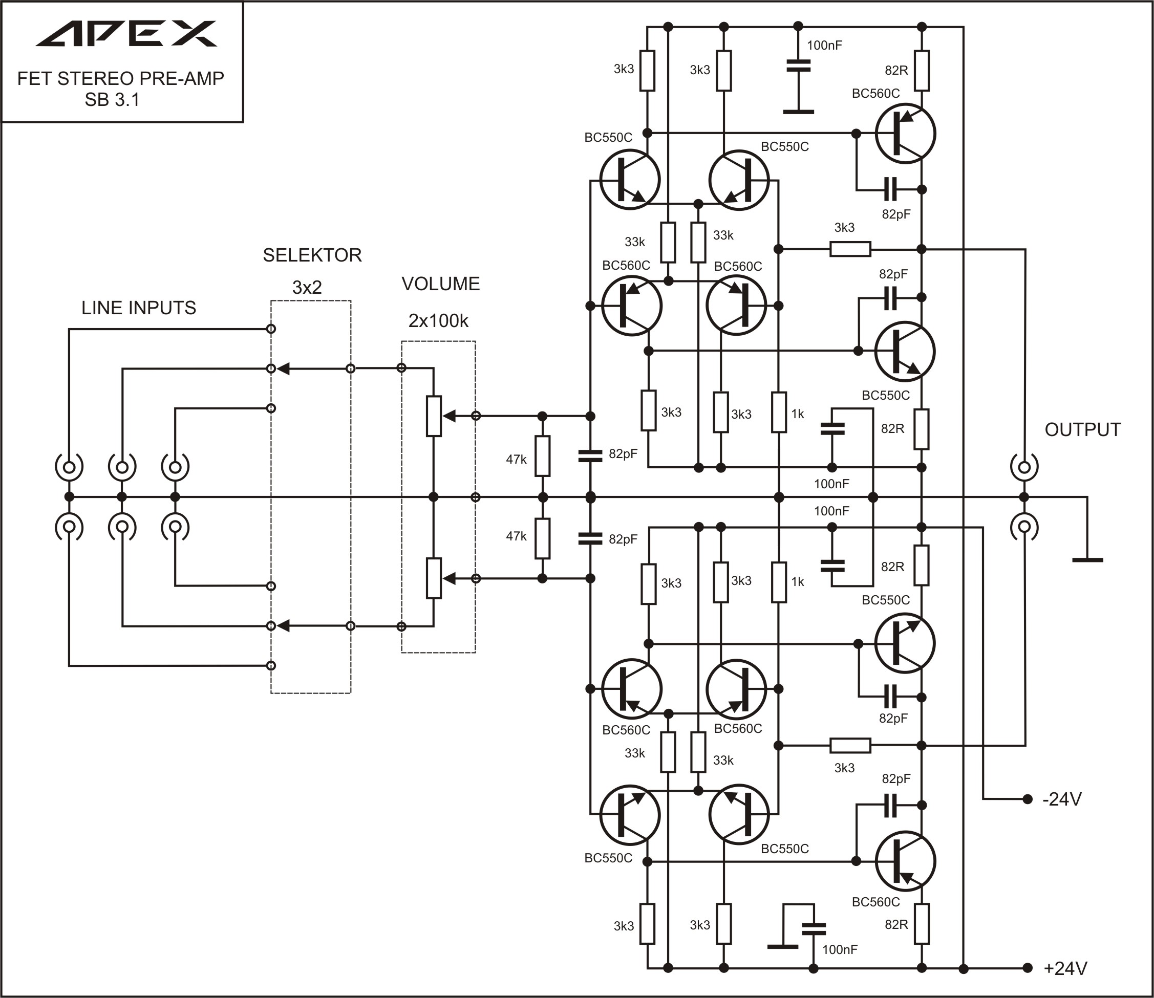
Note that I am using 100R vs 82R for the output stage and 100pF vs 82pF caps. I also added 100uF smoothing caps on PS rails (25v).
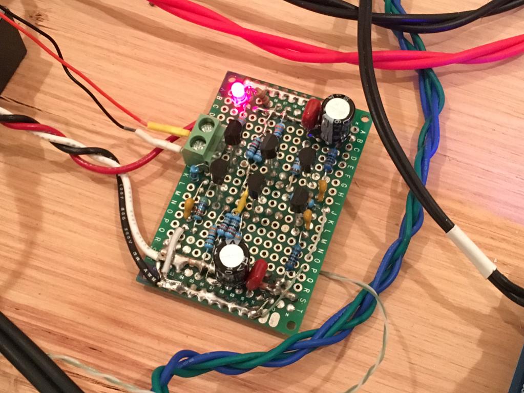
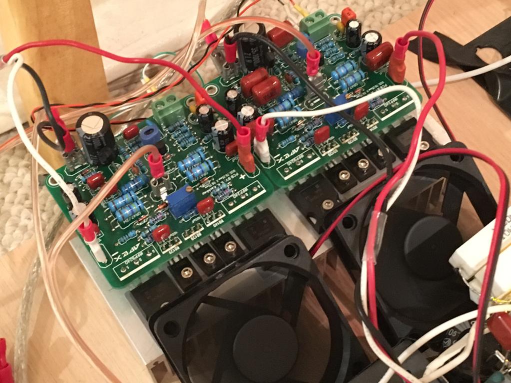
Here is the amp on veroboard (one channel only):
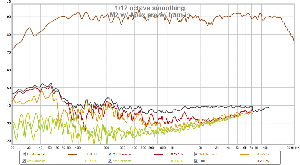
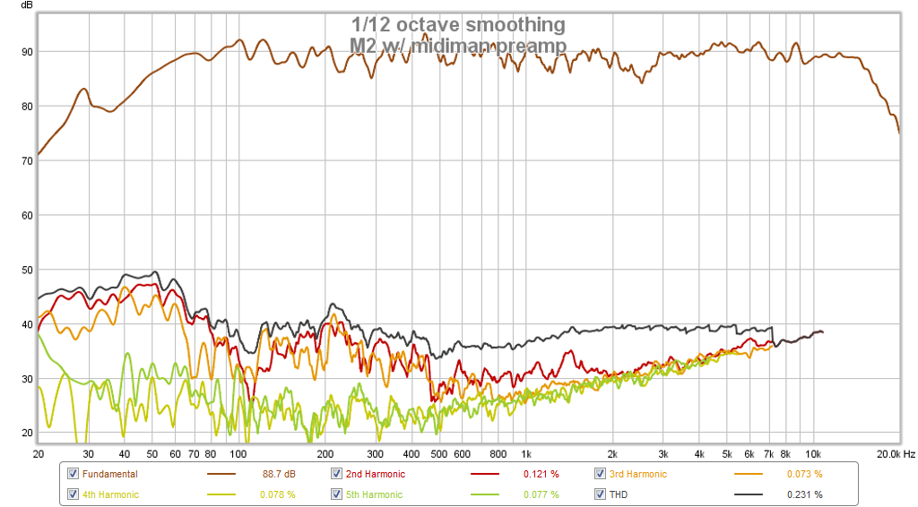
Here is measured response and HD at the speaker (mic measurement) vs a commercial preamp (cursor at 1000Hz):
Apex preamp:
Midiman 18 channel micromixer console as preamp:
Note that I witnessed burn-in again as initial measurements were a dissappointment in HD:

So my takeaway is to let an amp run for a while to work out it's magic (maybe something with the caps?).
I just built this simple little preamp (first desribed in this thread). It works really well - clean sound and just the right amount of gain for my Pass M2 class A amp that has only 14dB gain.
Schematic (as shown is about 10dB gain):
Note that I am using 100R vs 82R for the output stage and 100pF vs 82pF caps. I also added 100uF smoothing caps on PS rails (25v).
Here is the amp on veroboard (one channel only):
Here is measured response and HD at the speaker (mic measurement) vs a commercial preamp (cursor at 1000Hz):
Apex preamp:
Midiman 18 channel micromixer console as preamp:
Note that I witnessed burn-in again as initial measurements were a dissappointment in HD:
So my takeaway is to let an amp run for a while to work out it's magic (maybe something with the caps?).
Last edited:
Are you using bc 550-560 for this preamplifier?
Yes, 550C/560C
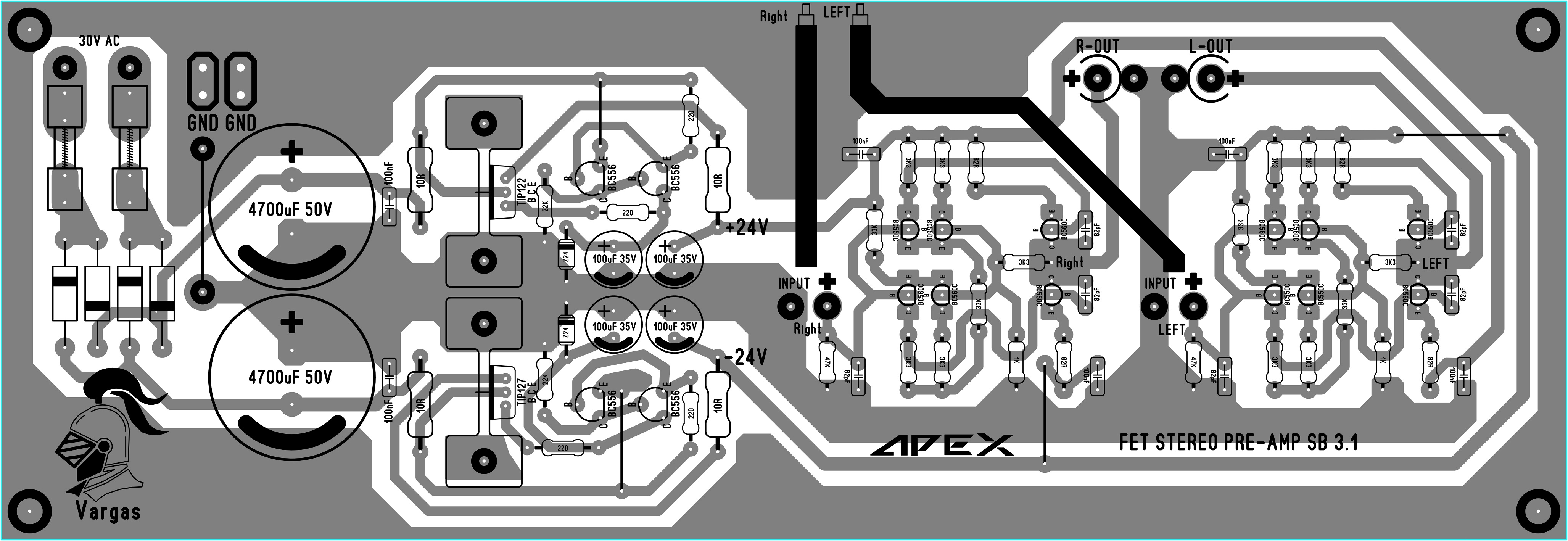
Someone must draw up a pcb for this preamplifier.😉Yes, 550C/560C
I agree. It's a gem - like many of Apex designs. With a PCB it would go very fast. As veroboard took some time to figure out how to get things to fit. I am using straight input via 680R vs a 100k input volume pot.
I think Vargasmongo had a PCB. Maybe he can share the Sprint file or Gerber with us? It would be good to get a really compact version sans power supply.
http://www.diyaudio.com/forums/soli...imate-fidelity-amplifier-448.html#post4259554
I think Vargasmongo had a PCB. Maybe he can share the Sprint file or Gerber with us? It would be good to get a really compact version sans power supply.
http://www.diyaudio.com/forums/soli...imate-fidelity-amplifier-448.html#post4259554
Last edited:
Sound clips of FH9HV:
http://www.diyaudio.com/forums/soli...y-simple-quasi-mosfet-amp-21.html#post4823060
This has got to be one of my best sounding amps! Very nice with 44v rails power supply.
http://www.diyaudio.com/forums/soli...y-simple-quasi-mosfet-amp-21.html#post4823060
This has got to be one of my best sounding amps! Very nice with 44v rails power supply.
Greetings mr.xrk
Fh9 singing with irf540&irf9540 good sounding amp
Fh9 singing with irf540&irf9540 good sounding amp
Attachments

Last edited:
This has got to be one of my best sounding amps! Very nice with 44v rails power supply.
X, please, add the schematic used
Hello X,
Where do you buy your veroboard????. I cannot find that style at any of my local electronic stores. If you can, please let me know the hole diameter.
Thanks,
Myles
Where do you buy your veroboard????. I cannot find that style at any of my local electronic stores. If you can, please let me know the hole diameter.
Thanks,
Myles
Hello X,
Where do you buy your veroboard????. I cannot find that style at any of my local electronic stores. If you can, please let me know the hole diameter.
Thanks,
Myles
But where else? Aliexpress... 🙂
4x6cm:
https://www.aliexpress.com/item/B13...-Printed-Circuit-Board-4x6cm/32351802217.html
$2.79 for 10 shipping included. The holes are a bit small and require drill out to fit terminal block. But capacitor big pins on 4700uF 63v elcos fit just fine.
Here is a bigger 7x9cm:
https://www.aliexpress.com/item/5PC...B-Double-Sided-7X9cm-70x90mm/32718733398.html
And 8x12cm:
https://www.aliexpress.com/item/8x1...rsal-DIY-Prototype-PCB-Board/32659191755.html
Last edited:
X, please, add the schematic used
Nice work, xrk971! I'm looking foreward my own amp (PCBs are on the way).
Looks like FH9(HV). In this case you should have the schematc, AdeS, or you can use this one with a FH11 PCB
Last edited:
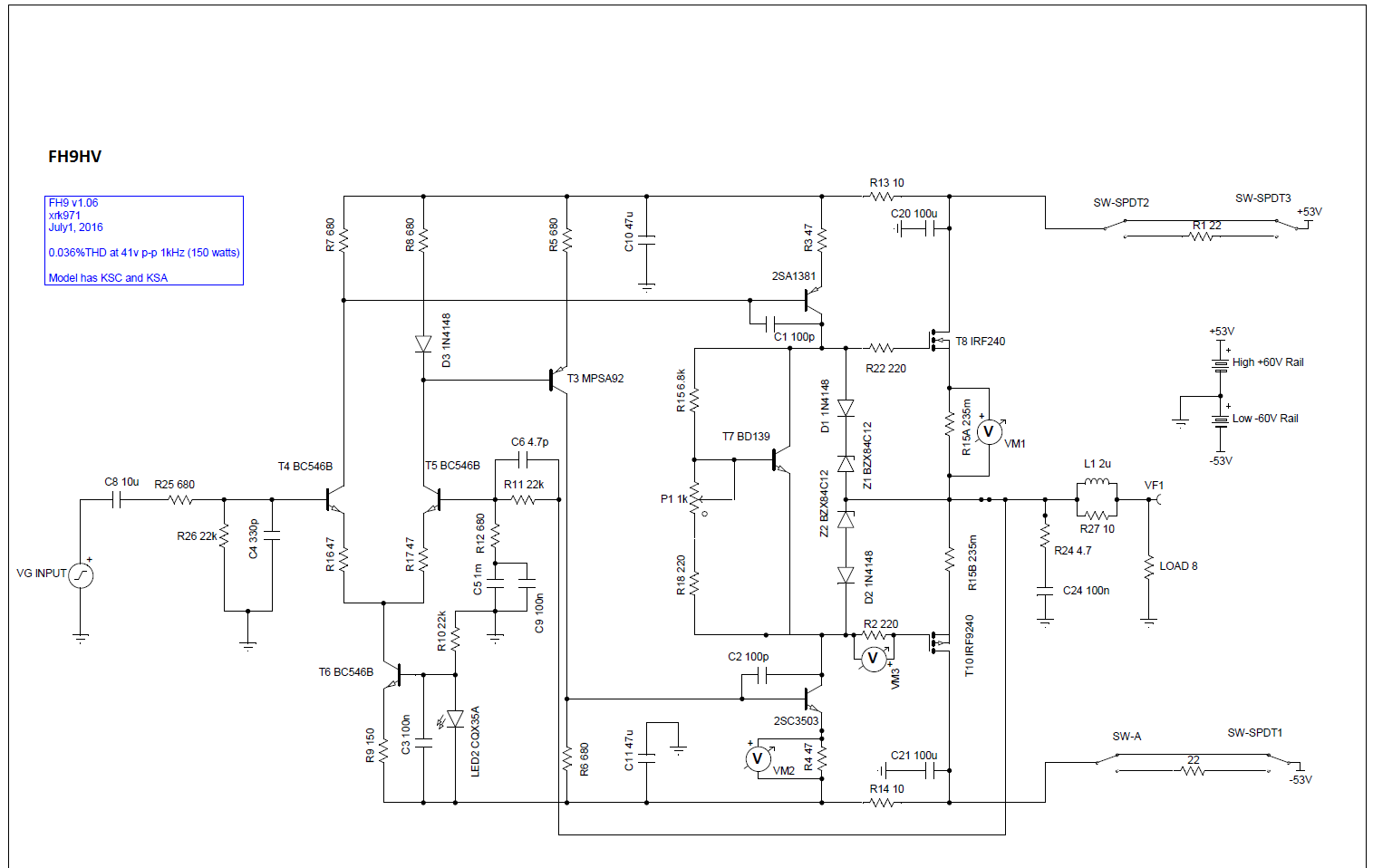
FH9HV Schematic and PCB files
It's in the Apex Directory thread. But that one is the standard version with BD139/140 drivers.
http://www.diyaudio.com/forums/solid-state/292226-directory-apex-audio-amplifiers.html
Here is updated schematic with KSC/KSA drivers (note that this is a slightly later version with LED on CCS for LTP - as used on FH11/12 so that is proven to work. Without it works fine too - just no visual indicator it's powered up):
Gerbers and layout here:
http://www.diyaudio.com/forums/soli...imate-fidelity-amplifier-746.html#post4718422
Just replace BD139/140 drivers with KSA/KSC parts and make sure all elco's can handle higher rail voltages.
X, please, add the schematic used
It's in the Apex Directory thread. But that one is the standard version with BD139/140 drivers.
http://www.diyaudio.com/forums/solid-state/292226-directory-apex-audio-amplifiers.html
Here is updated schematic with KSC/KSA drivers (note that this is a slightly later version with LED on CCS for LTP - as used on FH11/12 so that is proven to work. Without it works fine too - just no visual indicator it's powered up):
Gerbers and layout here:
http://www.diyaudio.com/forums/soli...imate-fidelity-amplifier-746.html#post4718422
Just replace BD139/140 drivers with KSA/KSC parts and make sure all elco's can handle higher rail voltages.
Attachments

Last edited:
Greetings mr.xrk
Fh9 singing with irf540&irf9540 good sounding amp
Interesting. Never thought to use 540's! Good to know it works well.
But where else? Aliexpress... 🙂
4x6cm:
https://www.aliexpress.com/item/B13...-Printed-Circuit-Board-4x6cm/32351802217.html
$2.79 for 10 shipping included. The holes are a bit small and require drill out to fit terminal block. But capacitor big pins on 4700uF 63v elcos fit just fine.
Here is a bigger 7x9cm:
https://www.aliexpress.com/item/5PC...B-Double-Sided-7X9cm-70x90mm/32718733398.html
And 8x12cm:
https://www.aliexpress.com/item/8x1...rsal-DIY-Prototype-PCB-Board/32659191755.html
You can also use this nice little software to help you design the veroboard (as you call them).
LochMaster
Ciao!
Do
The low-power version with irf9510 / IRF510 would be great.
low CISS
VAS would not suffer.
Thiago
low CISS
VAS would not suffer.
Thiago
You can also use this nice little software to help you design the veroboard (as you call them).
LochMaster
Ciao!
Do
Thanks! Never knew such a thing existed - gives realistic part placement diagrams and where to solder and jumper. Might be good for slightly more complicated projects - but then you might as well design PCB laout and get it fab'd for $10 in China.
Thanks! Never knew such a thing existed - gives realistic part placement diagrams and where to solder and jumper. Might be good for slightly more complicated projects - but then you might as well design PCB laout and get it fab'd for $10 in China.
There's a free demo version, although limited it allow you to do smaller circuits. Always good for prototypes.
Do
I agree. It's a gem - like many of Apex designs. With a PCB it would go very fast. As veroboard took some time to figure out how to get things to fit. I am using straight input via 680R vs a 100k input volume pot.
I think Vargasmongo had a PCB. Maybe he can share the Sprint file or Gerber with us? It would be good to get a really compact version sans power supply.
http://www.diyaudio.com/forums/soli...imate-fidelity-amplifier-448.html#post4259554
I will see if I can find the Sprint file I don't mine to share the files 🙂 maybe you guys can used as reference, I tend to make too big the PCB 😛
- Home
- Amplifiers
- Solid State
- 100W Ultimate Fidelity Amplifier