I don't care about distortions at clipping. But if LTP current is "signal dependent", then it alters global loop gain, and much worse things could happen. Please take into account, that after clipping, LTP tail current need some time to return to proper value, so it can alter distortions some time after clipping. As I said, it's probably harmless, but You should carefully check (not only in simulation).
Personally I take little care about clipping behavior at all - in my opinion signal should be limited before power amp, so it itself never go to clipping. That solution is far from perfect - You need limit early enough to be safe if power supply collapse at high load, or make the limiter supply voltage dependent - which can cause some undesired feedback. And of course You need to ensure that amp is clipping-proof anyway - no oscillations or too long "sticking".
You paid so much attention to clean clipping recovery, so I thing You should fix that little thing too.
My nag is that we don't even seem to know if there is a problem and whether the 47R resistors are the solution to it. I've never had oscillation problems that I needed to fix with base stoppers on the LTP.
I think if the 47R resistors were a solution, the oscillation would be in the 100s of MHz, because they are not very significant at any lower frequency. Furthermore the BC5xxC already has an internal base resistance of 150R or so.
I would attribute changes in risetime and step response due to these resistors not to small-signal stability, but to slewing/overload behavior.
I don't care about distortions at clipping. But if LTP current is "signal dependent", then it alters global loop gain, and much worse things could happen. Please take into account, that after clipping, LTP tail current need some time to return to proper value, so it can alter distortions some time after clipping. As I said, it's probably harmless, but You should carefully check (not only in simulation).
...
You paid so much attention to clean clipping recovery, so I thing You should fix that little thing too.
Dear wojtek,
you are right, I fully agree. I always appreciate your findings and ideas!
CCS dependency will be fixed in one of the next updates and need more investigation. E.g. D. Selfs blameless has slightly coupled CCSes.
BTW the CCS recovery time from negative half wave hard clipping is about 30 - 40ms.
BR, Toni
That may have been the reason which cured the MyDOA sensitivity and bettered the measurements......
I would attribute changes in risetime and step response due to these resistors not to small-signal stability, but to slewing/overload behavior.

Last edited:
Thanks for that, I did a simulation of the inner loop Return Ratio, at the VAS input.
Have you looked at this, in particular the PM?
Best wishes
David
Dear david,
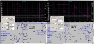
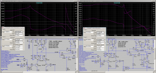
you are right. The simulation shows a relatively small PM in inner loop. Maybe "Rm2" is a bit oversized. If Rm2 is reduced from 100R to 68R the balance between inner and outer loop GM/PM values are looking better.
Note: The real hardware is pretty stable using 100R. I will verify if 68R does give any different measurement/hearing results the next days/weeks.
Thank you for reporting!
Simulating the inner loop using the "Tianprobe" does give a weird 180 degree wrap around at 100kHz using enhanced VAS. Maybe one has an explanation for this effect (LTSpice bug? Who knows?).
BR, Toni
Attachments
Last edited:
...Note: The real hardware is pretty stable...
It looks acceptable in simulation too, especially when it is validated with real tests. But it's always nice to improve.
One idea that you could retry is TPC. The extra load that it imposes compared to TMC can sometimes actually act as a little helpful shunt compensation.
One lesson I have worked out is that with more gain in the VAS then more difference between the two TPC capacitors can be useful.
... a weird 180 degree wrap around at 100kHz ... Maybe one has an explanation for this effect (LTSpice bug? Who knows?)
I think what you shown is perfectly normal, you have a little Nyquist conditional stability between 100 kHz and 700 kHz. No problem.
Sometimes I do find LTSpice shows weird phase plots, apparently when there is a null of some sort and it decides the phase arbitrarily. I suspect these should be checked carefully but don't fully understand yet.
Best wishes
David
Last edited:
...
I think what you shown is perfectly normal, you have a little Nyquist conditional stability between 100 kHz and 700 kHz. No problem.
...
Ok
 - conditional stability - now the plot makes more sense compared to this link: loop-stability
Thanks, Toni
I don’t get why the phase is recovering at high frequency (40+ MHz) - what’s the explanation here? Is it a right-hand plane pole and is that a problem?
What happens if you extend the Sim to 1 GHz? Of course we need to remember that as you go above 100 MHz the model requires more and more parasitic elements (layout-specific) for the sims to have any basis in reality.
What happens if you extend the Sim to 1 GHz? Of course we need to remember that as you go above 100 MHz the model requires more and more parasitic elements (layout-specific) for the sims to have any basis in reality.
Last edited:
...(40+ MHz) - what’s the explanation here?
I don't pay too much attention once the frequency pushes up, for precisely the reasons you mention, but that's well spotted, it is a bit odd.
Toni's compensation is a little complicated, It's difficult just to understand TMC and TPC completely.
I am on an exercise to understand this second-order stuff.
Have you looked at Feucht's OPS stability papers or the application of Middlebrook's GFT in LTspice?
Best wishes
David
Last edited:
I don't pay too much attention once the frequency pushes up, for precisely the reasons you mention, but that's well spotted, it is a bit odd.
Stuff like that always makes me very wary!
I am on an exercise to understand some of this more complicated, second-order stuff.
Let us know when you figure it out! I’d love to study this in depth but I simply don’t have the time at the moment

Have you looked at Feucht's OPS stability papers
Refs?
or the application of Middlebrook's GFT in LTspice?
I use Frank Wiedman’s loop-gain probe (https://sites.google.com/site/frankwiedmann/loopgain) which I believe implements the GFT. This is another one of those things I’d like to study more as I’ve read conflicting things about who gets the “right” answer at HF - Middlebrook’s GFT or Tian et al.
Refs?
http://audioworkshop.org/downloads/AMPLIFIERS_OSCILLATION_BJT_CIRCUITS.pdf
In particular, where does the -ve capacitance in picture (b) on p.7 come from?
I use Frank Wiedman’s ... which I believe implements the GFT.
Yes I have studied Frank's work, very helpful.
I have modified his implementation to make it a little simpler but I still find the interpretation of results unclear.
The Intusoft/ICAP implementation has different versions for different uses and that just complicates the problem.
Best wishes
David
Last edited:
Ah, one of the many tech. notes that I have that look like they could be very informative, but I haven’t had time to study.
Ah, one of the many tech. notes that I have that look like they could be very informative, but I haven’t had time to study.
Yes, I expected that you would be familiar with Feucht's work.
He was one of the few sources on Two Pole Compensation other than yourself but takes a different approach that includes a few points you don't, and vice versa.
I found that worthwhile despite the fact that I find your work more readable.
So could I ask you to have a quick look at this article and see if you can follow where the -ve capacitance comes from?
I may have a vested interest but I do think you will find it informative
Best wishes
David
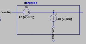
Toni, its not clear where your Tian probe is connected.you are right. The simulation shows a relatively small PM in inner loop. Maybe "Rm2" is a bit oversized. If Rm2 is reduced from 100R to 68R the balance between inner and outer loop GM/PM values are looking better.
Simulating the inner loop using the "Tianprobe" does give a weird 180 degree wrap around at 100kHz using enhanced VAS. Maybe one has an explanation for this effect (LTSpice bug? Who knows?).
Are the 2 plots of the same compensation method? Are you using the Tian probe from the LTspice library?
Also, if C18 (at the LTP i/p) is not connected, you can't guarantee stability if the i/p is open circuit. Even if the i/p is short circuited, the absence of C18 will lead to different stability conditions.
This is true both for LTspice as well as 'real life'.
Toni, its not clear where your Tian probe is connected.
Are the 2 plots of the same compensation method? Are you using the Tian probe from the LTspice library?
Also, if C18 (at the LTP i/p) is not connected, you can't guarantee stability if the i/p is open circuit. Even if the i/p is short circuited, the absence of C18 will lead to different stability conditions.
This is true both for LTspice as well as 'real life'.
think, Dave wanted to save "virtual wires"
- see attached pictures (labels "vas-inp" and "x"). The 2 plots are using the same circuit and the same compensation only "Rm2" was changed from 100R to 68R. Left plot is outer loop stability, right plot is inner loop stability.
If C18 is connected, the stability betters a few db (for me it's not clear why).
The "Tianprobe" is from LTspice lib. I have added this function to the "plot.defs" file:
.func TianProbe() {-1/(1-1/(2*(I(Vi)@1*V(x)@2-V(x)@1*I(Vi)@2)+V(x)@1+I(Vi)@2))}
BR, Toni
Attachments
... Even if the i/p is short circuited, the absence of C18 will lead to different stability conditions.
This is true both for LTspice as well as 'real life'.
Hi, you have been a bit quiet!
Toni and I swapped a few emails on exactly this subject just a few days back.
I had earlier been surprised at how much the loop gain. was affected when I added an "RF filter" to the input.
At least, I intended an RF filter, the improved stability was a bonus.
I didn't think of it as "in the loop", do you have a simple qualitative explanation for this?
Best wishes
David
Remember that in conduction, a BJT's B-E capacitance increases greatly, and is in addition to the 90 degrees LTP output current which appears as a capacitive Ib of the LTP. A BC550C LTP can have a real and/or virtual 400pF or so across the bases while conducting. The datasheet Cib curves are for a REVERSE-biased B-E junction - it actually increases with Vbe.
At RF, the base current through this capacitance is significant. So say your effective differential capacitance through the LTP bases is 400pF. You use a 390pF input decoupler or LP filter. Well, if you have no source connected and the input isn't shorted, then the input differential capacitance forms a capacitive voltage divider and your LTP transconductance at RF is halved!
Hopefully that makes sense, or provides enough information you can replicate it in simulation.
The source impedance at RF is very much "in the loop", and the same applies for the feedback side of the LTP. It gets much more important when you push the ULGF high.
Last edited:
- Home
- Amplifiers
- Solid State
- 2stageEF high performance class AB power amp / 200W8R / 400W4R