Hi PB,
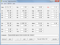
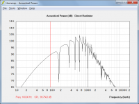
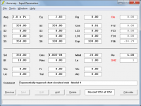
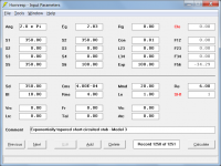
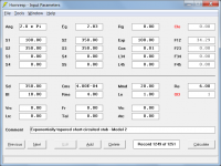
When the 'resonances not masked' option is selected both sealed box and closed transmission line systems are analysed the same way by Hornresp. This can be confirmed by comparing a sealed box with an untapered closed transmission line system of the same dimensions. As shown in the attachments the 'resonances not masked' results are identical. Tapering a closed transmission line simply alters the calculated acoustical impedance loading the rear side of the driver diaphragm. The simulation model itself does not change.
Kind regards,
David
Thank you for the quick response! This makes sense.
The closed TL is a really interesting feature, I'm surprised more people haven't used it.
This is hideously complex, obviously. But hooray for Hornresp, because I'm not aware of any other way to model a closed back transmission line, except for Akabak. Which has been abandonware for 10+ years.
There is new Akabak3 that is 64bit compatible and completely different in that it’s not script based anymore but blocks and circuit strings. I have not personally used it as I have hundreds of script/code snippets that I have developed with Akabak1 and so I use a VM to run it on WinXP.
AKABAK 3

Folding a geometric series like I did for the square block FP channels was very easy. They all line up perfectly. A logarithmic series is a pain. There is an entire subset of mathematics focused on optimal packing of different geometries. You could also build a linear optimization routine to brute force it.
All that to say, just do it manually. It isnt that bad to keep track of a few dozen tube lengths. If you wanted a fully parametric routine to make the tubes that is a different story, with that I wish you luck.
All that to say, just do it manually. It isnt that bad to keep track of a few dozen tube lengths. If you wanted a fully parametric routine to make the tubes that is a different story, with that I wish you luck.
If you look at the performance of the old design, it's superior. My hunch on why the old one works better than the new one, is that I think that a fraction of the incoming soundwave is reflected by the exit of the transmission line, while a fraction of it exits. I think this explains why the old one is much broader in spectrum.
I dont think thats it. Rather i think laminar flow resistance can become of importance and acoustic losses occur. Computational fluid dynamics may be necessary for a rigorous analysis of these phenomena. The ratio of circumference to cross-sectional area is large for small TLs (and ports), and the boundary layer of air in contact with the walls drag against them, and the boundary layer in contact with the previous layer does the same, etc. I think these losses could be purposfully used to damp and tune down the TLs - instead of using any stuffing - if the transmissionlines have high circumference/CSA-ratios, or if they are really small. The older design had a higher ratio. KEF uses 2mm TLs.
The closed TL is a really interesting feature, I'm surprised more people haven't used it.
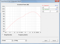
The closed TL is similar to a short-circuited stub. There are a number of ways that it can be modelled in Hornresp, as shown in the attached examples. The results will be the same for each model. Absorbent filling material can be added using the Loudspeaker Wizard.
Attachments
Last edited:
Sent a DM, but as your active in the thread:
"The Peerless DA25BG08-06 looks like a great candidate for testing, thanks for the heads up. Was looking at the tweeters I have used and considered using in the future and they all look like a massive pain to open up.
Do you have any pictures of the tweeter opened up? If you still have one would you be willing to open it and take measurements (the diameter of the throat at the exit would be the minimum)? Basically what is needed is a clear shot to the diaphragm out the back of the magnet for the meta material to work."
I have started to model a meta material with a 19mm diameter throat for broad band damping of a tweeter like the DA25BG8-06 (assuming the diameter for now).
Here is a script (MATLAB or Octave) I wrote to find the lengths of the FP tubes on a log scale. I have it set to find me 32 tubes tuned to the 1/4 wave between 400 and 6k Hz at the nearest 0.25 mm.
Here's those pics you requested. In particular, the throat opening is 15mm and 'necks down' to about 12.7mm after a chamfer at the entrance.


Thanks for the measurements and photos. Did bring up the quest to me, is that faceplate removable or is it attached to the diaphragm assembly. Would effect waveguide integration. Originally looked like a 4 bolt SB Acoustics compatible waveguide may work with it.
Noticing that the 12.7mm throat opens back up to what I am assuming is a 25.4mm. Presents several opportunities to try different inlets to a meta material. Could extend the 12.7mm bore with an insert, could have a flat plate inlet at 25.4mm, or like the kef design with 12.7mm or 25.4mm. I would start with a very simple no turn design at 25.4mm inlet with as many ~25mm2 tubes as possible. Would be tall, but easy print and design.
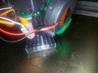
Here is an image of my test prints for my metamaterial models. Tape for scale and keyboards have a .75" or 19.05mm spacing between keys. Printed at 50mm/s on the walls (they are all exterior walls so you may need to change slicer settings) with 0.2mm layer height and 0.4mm nozzle. Real print time for both is about the same at about 12-13h. So far subjectively just aiming a headphone speaker at them and listening from behind the speaker the tall FP tube one seems to have a greater effect in comparison to a flat plate (simulated by my cell phone). The labyrinthine one may need additional layers.
Noticing that the 12.7mm throat opens back up to what I am assuming is a 25.4mm. Presents several opportunities to try different inlets to a meta material. Could extend the 12.7mm bore with an insert, could have a flat plate inlet at 25.4mm, or like the kef design with 12.7mm or 25.4mm. I would start with a very simple no turn design at 25.4mm inlet with as many ~25mm2 tubes as possible. Would be tall, but easy print and design.
Here is an image of my test prints for my metamaterial models. Tape for scale and keyboards have a .75" or 19.05mm spacing between keys. Printed at 50mm/s on the walls (they are all exterior walls so you may need to change slicer settings) with 0.2mm layer height and 0.4mm nozzle. Real print time for both is about the same at about 12-13h. So far subjectively just aiming a headphone speaker at them and listening from behind the speaker the tall FP tube one seems to have a greater effect in comparison to a flat plate (simulated by my cell phone). The labyrinthine one may need additional layers.
Attachments
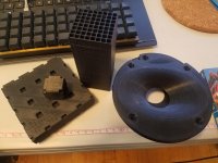
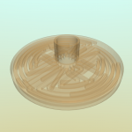
Got a tweeter metamaterial disk made up. Effective 620Hz to 6.2kHz center frequencies, 32 2mmx2mm FP channels with log spacing using the script I posted earlier. Inlet throat is 12.7mm, overall diameter 70mm. Should fit nicely in the standard driver cutout or behind a waveguide.
For the DA25BG08-06 specifically you will want to continue the narrower 12.7mm throat out to the metamaterial with a tube either fully filling the larger rear chamber (like with a wood puck with a donut hole) or stuffing around the tube. A small bit of foam or polyfill should be placed in the metamaterial's central cavity to smooth the filtering.
I printed it out of PETG for the see through effect, but I would suggest PLA or ABS/ASA. PETG has those little boogers that can get caught in the channels.
STL File for 3d printing:
FP_Disk_127.stl - Google Drive
Attachments
Got a tweeter metamaterial disk made up. Effective 620Hz to 6.2kHz center frequencies, 32 2mmx2mm FP channels with log spacing using the script I posted earlier. Inlet throat is 12.7mm, overall diameter 70mm. Should fit nicely in the standard driver cutout or behind a waveguide.
For the DA25BG08-06 specifically you will want to continue the narrower 12.7mm throat out to the metamaterial with a tube either fully filling the larger rear chamber (like with a wood puck with a donut hole) or stuffing around the tube. A small bit of foam or polyfill should be placed in the metamaterial's central cavity to smooth the filtering.
I printed it out of PETG for the see through effect, but I would suggest PLA or ABS/ASA. PETG has those little boogers that can get caught in the channels.
STL File for 3d printing:
FP_Disk_127.stl - Google Drive
This is awesome!
I need to print this.
Made some edits to help with printability and to better isolate the tweeter from any woofer it may share the cabinet with. The bottom/back was only 1mm thick, bumped that up to 3mm, lends better dimensional consistency further from the build plate for the channels. Increased diameter to 72mm, extra 1mm material all the way around.
STL download:
FP_Disk_128.stl - Google Drive
For a real application I am thinking you may want to stay away from PLA. It suffers from creep and being right on the motor structure is not ideal for that. Checked on nylon MJF and it would be about $24 each, which is basically the cost of our test candidate tweeter... but hey its will be cool. PLA should be fine for testing.
I have built a "metamaterial" design loudspeaker.
I did not use 3D printing, though. Nor does it fit a tweeter. It is for midrange, instead. But the same principle.
CORONA: A Big Metamaterial Enclosure -
Techtalk Speaker Building, Audio, Video Discussion Forum
I did not use 3D printing, though. Nor does it fit a tweeter. It is for midrange, instead. But the same principle.
CORONA: A Big Metamaterial Enclosure -
Techtalk Speaker Building, Audio, Video Discussion Forum
WOW!!
Reading your writeup, I got thinking of a spherical version of the Corona: Hula-Hoops in a radial array, but sweeping backward to form an impractical sphere.. The hoops could be put in series to get to that 9' length target.. And maybe there are enough arcs to drape fiberglass/epoxy and make a spherical form, like the IKEA Blanda bowl speakers. Nice for diffraction, and tempting to try to make some Isobaric subwoofer out of that volume")
Reading your writeup, I got thinking of a spherical version of the Corona: Hula-Hoops in a radial array, but sweeping backward to form an impractical sphere.. The hoops could be put in series to get to that 9' length target.. And maybe there are enough arcs to drape fiberglass/epoxy and make a spherical form, like the IKEA Blanda bowl speakers. Nice for diffraction, and tempting to try to make some Isobaric subwoofer out of that volume
Here's a pic describing what I meant from post 53. Basically a poorly terminated Paraline will have deep nulls, caused by reflections. The reflections are due to an impedance mismatch. Normally, that's a BAD thing, but if you're TRYING to make something that nullifies sound, that could be good. Particularly if you can build 15-30 of these, all tuned to different resonances.
Again, this performance is not typical of a well built Paraline; this Paraline basically had no termination, which leads to harmonic dips in the response, caused by higher order modes.
The jagged line is my poorly built paraline, the smooth line is a qsc waveguide, both devices were driven by the same compression driver with the same voltage.
Someone sent me a message asking how to do a Closed Transmission Line. Here's how:
"Double-click the Cir or Fta label in edit mode to select the Clo closed horn mouth option. Not applicable to direct radiator loudspeakers, tapped horns or single segment horns other than Con, Exp or Par."
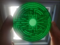
So I printed this last night, but I don't think it's going to work in the real world. The channels are something like 2mm in diameter, and I think that's too fine.
For instance, the nozzle on my 3D printer is 0.8mm, and when I printed it, a significant number of the channels are impeded by stringing and just a general lack of accuracy.
The obvious solution would be to reduce the nozzle size to 0.4mm, but when I do that, my printer always jams.
The other solution would be to do it in ABS. Which I may try today.
Ideally, I'd love to carve out a few hours and redesign this thing, so that the diameter of the channels is about 4-5mm.
It's not as simple as scaling the 3D model, because if I scale it, it will change the resonant frequencies of the channels.
Another option might be to scale the model on one axis only. This would increase the volume without changing the resonant frequencies.
Are you going to test this? Maybe replace the rear cover of a tweeter?
Patrick, probably what I would do for dimensionally accurate application is laser cut this in layers of acrylic or FR4 and bond them. I had good success with a quality PLA+ on this model, PETG while pretty in that picture was not viable with the stringing. I kept things that size so it would fit on the back of a standard 72mm diameter tweeter. You might be able to increase the aspect ratio of the channels out to 1.2-.5, but ofc that will mess with the impedance.
.8 mm nozzle is a no go for this model, .4 or less. You can adjust your extrusion width to .6 mm with a .8 and maybe get a better result.
For my current build I decided on a tweeter without an easily removed backcup, so won't be testing myself for a while.
.8 mm nozzle is a no go for this model, .4 or less. You can adjust your extrusion width to .6 mm with a .8 and maybe get a better result.
For my current build I decided on a tweeter without an easily removed backcup, so won't be testing myself for a while.
Last edited:
That is a GREAT idea!
Personally, I like my laser cutter a lot more than my 3D printer, so I'm always itching for an excuse to use it.
If you ever get a chance to post the original model, please do. You posted the STL, but it wasn't water-tight, so I don't have any ability to make changes to it.
Another option would be two SVG files, one for each of the two layers in your model.
- Home
- Loudspeakers
- Multi-Way
- 3D Printed Metamaterials