Luckily my midranges are no living species. But that is exactly what I mean, wide acceptance could be caused by distortion issues that are welcomed by the audience. We’ve seen that one before.The larger it can be, the better the mids can breathe. This is accepted lots of places.
What would a bigger enclosure add besides a weaker air spring, cavity resonances at frequencies where you don’t want them and, if not incorporated in a main enclosure, more panel resonances? The only issue is that the enclosure has to be big enough to prevent air compression nonlinearities.
Since I've heard a few pair designed this way, I would say it has the tendency to, more often than not, NOT affect the tonality of the midrange driver. It is a very low Qtc sealed box. For example, using too small or stuffed will stifle the openness and choke off the driver at times. It can also produce peaks or cavity resonances that the larger can avoid. Additionally, I have used drivers as midranges that others have used in different chambers, and the difference in sound between them was pretty shocking. Of course, it varies strongly driver to driver, and moreso in effect the lower the midrange plays. While I don't necessarily feel a box this large is required for good midrange it is a good approach.
Lastly, I feel that multichamber aperiodic boxes produce fantastic midrange, and some of the most open and clear mids I've achieved.
Lastly, I feel that multichamber aperiodic boxes produce fantastic midrange, and some of the most open and clear mids I've achieved.
What would a bigger enclosure add
as you enlarge the enclosure you go towards open baffle
try your mid on an open baffle
bigger enclosure add ............ cavity resonances at frequencies where you don’t want them
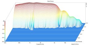
do you have some comparative data on this? say freq/imp data?
@Bmsluite I'll give you an example. Let's say that you want to crossover from the mid to the woofer at 300 Hz
with a Linkwitz-Riley 4th order crossover type. You need to consider that the crossover response is the cascade
of the driver electro-acoustical rolloff with the response of the electrical crossover. An LR4 is also called Butterworth (B2)
squared because it is the cascade of two B2 sections. Since a sealed box driver rolls off as a second order response
the logical thing to do is to size the chamber to shift the Fs of the driver up to an in box Fc of 300 Hz. This will
raise the in box Qtc well above the Qts of the driver. A B2 has a Q of .707 and this is what you want as a target
Qtc for the mid in chamber. Add stuffing to obtain the target Qtc. If the Qtc is too low you can use a high DCR
inductor in the crossover to raise the Qtc.
There will be cavity resonances but the fill in the chamber will damp them out.
Simple - yes?

@Bmsluite
Thanks, if you tell me more about your design goals I can try to help.
The final Qtc might end up too high, if your design needs baffle step compensation
you can use the mild gain of a Qtc over .707 to help provide the compensation so
there's less needed in the crossover - every dB helps.
If you can't get Fc and Qtc where you want them, there might be a better choice
for a midrange or you could target another XO frequency that works better.
That's a nice driver, do you plan to notch the high frequency peak?
What I described above is also discussed in S. Linkwitz's old paper with active crossover
something like "A Three Enclosure Loudspeaker". An example of what he does is let's
say you have a tweeter with a 1KHz Fc and you want to use it as part of an LR4 filter at
2 KHz he uses a fancy active filter "Linkwitz Transform" to effectively move the Fc to
2KHz and even retarget the Qtc to a new value of .707. Very clever:
https://www.linkwitzlab.com/Removed pages/x-sb80-3wy.htm
Are you using active or passive crossovers?
Honestly, a lot of what you just said went over my head. I have only desinged a couple different things so far.
I made a 3 way from traces for my bedroom
A desktop two way
A pair of full rangers for the my shop pool room
A folded horn full range for the kitchen
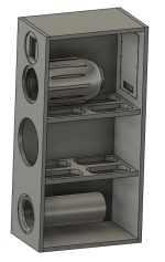
So this is my first major build. The goal is detailed, full range sound. We only sit in a couple places in the room these will be in so 15 degrees off axis dispersion is all I am really aiming for. This is for our TV where we spend the majority of our time yet currently has our worst sound system.
If you look at the box you'll see a removable back plate so this will allow me to mess with the crossover as I'm sure I won't get it right the first time around. I think I will also get a WIIM amp so I have a bit of active DSP and an EQ
The drivers are here:
Planar tweeter: https://www.parts-express.com/HiVi-RT1.3WE-Isodynamic-Tweeter-297-421?quantity=1
Mid range: https://www.madisoundspeakerstore.c...aph-audio-za14w08-5-aluminum-cone-mid/woofer/
Woofer: https://www.parts-express.com/Peerless-830667-8-Paper-Cone-SLS-Subwoofer-264-1102?quantity=1
I did check from traces that these drivers would work well together. I know it would be best if I had 2 woofers but the wife acceptance factor deemed that unattainable.
So I am very much a noob in this department. In manufacturing and engineering I am very well versed as that is my profession. I started this journey because I realized I knew very little about frequency and how music is produced from drivers. I am just here to learn and am having a lot of fun doing this.
I made a 3 way from traces for my bedroom
A desktop two way
A pair of full rangers for the my shop pool room
A folded horn full range for the kitchen
So this is my first major build. The goal is detailed, full range sound. We only sit in a couple places in the room these will be in so 15 degrees off axis dispersion is all I am really aiming for. This is for our TV where we spend the majority of our time yet currently has our worst sound system.
If you look at the box you'll see a removable back plate so this will allow me to mess with the crossover as I'm sure I won't get it right the first time around. I think I will also get a WIIM amp so I have a bit of active DSP and an EQ
The drivers are here:
Planar tweeter: https://www.parts-express.com/HiVi-RT1.3WE-Isodynamic-Tweeter-297-421?quantity=1
Mid range: https://www.madisoundspeakerstore.c...aph-audio-za14w08-5-aluminum-cone-mid/woofer/
Woofer: https://www.parts-express.com/Peerless-830667-8-Paper-Cone-SLS-Subwoofer-264-1102?quantity=1
I did check from traces that these drivers would work well together. I know it would be best if I had 2 woofers but the wife acceptance factor deemed that unattainable.
So I am very much a noob in this department. In manufacturing and engineering I am very well versed as that is my profession. I started this journey because I realized I knew very little about frequency and how music is produced from drivers. I am just here to learn and am having a lot of fun doing this.
Attachments
The boxes are getting CNC cut this weekend. One of my coworkers and 48" square CNC in his garage. These don't need to play loud. They will likely play at 1-10 watts their entire existence.I'd go with a 10 or 12" woofer since for all the complexity the 8" will be a limiting point.
You could side mount it or are the boxes built?
Or will you also use subs for HT?
I'll just dumb down the tweeter and mid with L pads and such to level it all out.
I did make provisions in the back plate so that each driver has its own set of terminals. This makes it way easier for me to take measurements and it makes it so that I can run it active in the future if I ever decide to do that. Ive put quite a lot of thought into this design. Burned about 4 rolls of various 3d printing filament making all the stuff. Even the tweeters have their own little mini enclosure to protect them from the back waves of the woofer.
Now when we start to use 3D printers, why not do a more ideal enclosure that just a basic "cup"?
The "dagger" comes to mind, the Nautilus snail and/or some meta material?
//
The "dagger" comes to mind, the Nautilus snail and/or some meta material?
//
TNT,
FDM printing is not capable of making such objects easily. You would need a resin printer. Currently a $4k resin printer has a print volume of 200mm cubed. Even my industrial FDM only has a print volume of 330 cubed.
Printers also cannot print in midair. They need supports. Supports scar the surface.
So a Nautilus is all but impossible to print unless you want to glue and sand and paint for hours on end. You'd be better off making a mould with 3d printing and then casting your object from that.
- Home
- Loudspeakers
- Multi-Way
- 3d Printed Mid Enclosure - Should I stuff it?