AllanB,
Well put AllenB.
I noticed the driver versus diameter in the Excel simulation.
Until measurements of an actual driver on an appropriate IEC baffle are taken and then placed on your ideal baffle shape these academic discussions are not going to solve any.
Looking at the big picture the TO has to be able to fabricate whatever the baffles end up being as a form factor.
The main function of the baffle is to secure the drivers.
The overall stability and rigidity of the entire assembly is quite important so that the tweeter or kept absolutely stable.
This will depend on how the other driver baffles or sub baffles are secured or fastened. Rocking of the enclosure is also important.
I think the use of a 3D printer if used for prototyping the round over shapes or trying different shapes will help arriving at some conclusions.
My own inclination is that a smooth changing form factor would offer a a suitable baffle shape as the width is constantly changing.
A 3D printer might be useful to flush mount the drivers and create a round over.
Attachments
By lateral mode, I assume you mean the radial mode? The mode driven by the diameter of the cylinder, not the mode driven by the depth (length) of the cylinder ?What if the lateral mode is not excited?
If there were a way to not excite the radial mode, yes that would be great. I am not sure how that would happen... ?
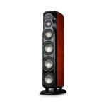
B&W Nautilus speaker and Vivid Giyas (from same designer) utilize smart shape both in- and outside. Only problem is round transsection.
https://www.bowerswilkins.com/en-us/product/loudspeakers/nautilus-series/nautilus/150016.html

https://www.bowerswilkins.com/en-us/product/loudspeakers/nautilus-series/nautilus/150016.html
Hello Ian
WRT baffle shape you can see that on the Revel Salon 2 where it is blended to reduce diffraction and a more uniform polar response.
Rob")
We agree. The truncated driver frames are useful. The shapes are almost elliptical.
The uniformity in the cross over region is likely more important than we realise when looking at polars 15,30,45, 60. You see it in global coloured plots.
Last edited:
I was thinking it through in a simplistic way and found this page which is quite useful. The article breaks down the problem.
https://www.speakerdesign.net/audio...=The Problem,and baffle edges and protrusions.
What is diffraction
What is the link to subjective perceptions
Solutions
Diffraction effects
What l agree with in the article are time domain related issues. The invisible problems. Diffraction ripples are visible and can be EQ in dsp but the time domain problem is still there.
“A sound wave will diffract when it encounters one of the obstructions mentioned. This causes interference with the main sound wave that is traveling outward toward the listener. This interference is delayed in time from the main sound wave and is a function of the distance to the diffracting obstruction (such as the baffle edge). It arrives at the listener position, altering the perception of the sound, since its arrival is close enough in time that you perceive it as being part of the main sound wave.”
Secondly, drilling down on the effects it’s soon becomes apparent that two closely spaced drivers can create obstructions.
Ie A dome shaped diaphragm obviously protrudes from the baffle. I hear a scoff from dome advocates. But these are the realities of weighing up the choices in a loudspeaker design and construction
Diffraction Effects
The impact of diffraction is highly dependent on several factors:
I hope this brings some clarity to the TO in arriving at a rational be or a simulation or empirical derived solution. Personally l think well founded explanations such as this link provide the basis for the diy builder to make informed choices.
On the other hand a simulation requires specific knowledge to use it and interpret the results correctly. The unknown unknowns may still escape you.
This is where an former supported by solid explanations provide a real test and learning ground.
Diffraction Effects
The impact of diffraction is highly dependent on several factors:
https://www.speakerdesign.net/audioXpress/diffraction/diffraction.html#:~:text=The Problem,and baffle edges and protrusions.
https://www.speakerdesign.net/audio...=The Problem,and baffle edges and protrusions.
What is diffraction
What is the link to subjective perceptions
Solutions
Diffraction effects
What l agree with in the article are time domain related issues. The invisible problems. Diffraction ripples are visible and can be EQ in dsp but the time domain problem is still there.
“A sound wave will diffract when it encounters one of the obstructions mentioned. This causes interference with the main sound wave that is traveling outward toward the listener. This interference is delayed in time from the main sound wave and is a function of the distance to the diffracting obstruction (such as the baffle edge). It arrives at the listener position, altering the perception of the sound, since its arrival is close enough in time that you perceive it as being part of the main sound wave.”
Secondly, drilling down on the effects it’s soon becomes apparent that two closely spaced drivers can create obstructions.
Ie A dome shaped diaphragm obviously protrudes from the baffle. I hear a scoff from dome advocates. But these are the realities of weighing up the choices in a loudspeaker design and construction
Diffraction Effects
The impact of diffraction is highly dependent on several factors:
- Baffle dimensions (height and width)
- Baffle edge geometry (square, roundover, chamfer, and so on)
- Driver position on the baffle
- Driver directionality
- Adjacent driver size and diaphragm shape
- Obstructions on the baffle (as in a stepped baffle)
I hope this brings some clarity to the TO in arriving at a rational be or a simulation or empirical derived solution. Personally l think well founded explanations such as this link provide the basis for the diy builder to make informed choices.
On the other hand a simulation requires specific knowledge to use it and interpret the results correctly. The unknown unknowns may still escape you.
This is where an former supported by solid explanations provide a real test and learning ground.
Diffraction Effects
The impact of diffraction is highly dependent on several factors:
- Baffle dimensions (height and width)
- Baffle edge geometry (square, roundover, chamfer, and so on)
- Driver position on the baffle
- Driver directionality
- Adjacent driver size and diaphragm shape
- Obstructions on the baffle (as in a stepped baffle)
https://www.speakerdesign.net/audioXpress/diffraction/diffraction.html#:~:text=The Problem,and baffle edges and protrusions.
Yes, the radial mode. Imagine the driving diaphragm applied even pressure over the cross section of the cylinder, all energy would travel down it's length regardless of frequency. The wavefront would be plane, without higher order modes.By lateral mode, I assume you mean the radial mode? The mode driven by the diameter of the cylinder, not the mode driven by the depth (length) of the cylinder ?
If there were a way to not excite the radial mode, yes that would be great. I am not sure how that would happen... ?
Perhaps you meant to say 'increases' diffraction, since more energy is going behind..on the Revel Salon 2 where it is blended to reduce diffraction and a more uniform polar response.
Perhaps you meant to say 'increases' diffraction, since more energy is going behind..
Well there is a paradox, I look at diffraction as destructive as in nulls and peaks. Any geometry that gives you a smooth on axis and polar I would think reduces diffraction. I guess it's you point of view?
Rob
Ok yes, i can imagine that. I wonder if the plane waves would remain planar in practice? or would the radial mode be energized eventually with a sustained signal? could this phenomenon be used in speaker cabinet design?Imagine the driving diaphragm applied even pressure over the cross section of the cylinder, all energy would travel down it's length regardless of frequency. The wavefront would be plane, without higher order modes.
Defining diffraction as something that looks worse? .. Diffraction isn't always unintended, in fact it should be planned wherever it is predicted, and recognised to be unavoidable.Well there is a paradox, I look at diffraction as destructive as in nulls and peaks. Any geometry that gives you a smooth on axis and polar I would think reduces diffraction. I guess it's you point of view?
Not to forget that even after polar response has been considered, timing and related spatial issues remain.
If they start out perfectly, although that's never true in practice but you can still have it be 'significantly' the case. Nothing will change over time since the waves simply pass and don't come back.. unless there is reflection from the end of the pipe, although that won't be at the same level and it could still be significantly planar.I wonder if the plane waves would remain planar in practice?
A transmission line enclosure or voigt pipe might be a common example of it being exploited. Only the first mode is of importance and higher order energy might unfortunately be wasted. In a regular cabinet it is trivial to just damp everything, but in a transmission line damping is used to control the primary mode, not eliminate it. It's just fortunate that stuffing can pull double duty on higher modes, or unfortunate if you consider that a designer might not wish to concern themselves with all this.
Baffle edge diffraction widens horizontal directivity by creating secondary source(s), which cause interferences. Because net radiated energy is constant, on-axial spl drops and off-axis spl increases, or vice versa.
Because a loudspeaker uses wide bandwidth/wavelength, we see wiggles in spl response and uneven directivity spectrogram.
Modern discussion is concentrated on crossover-related directivity problems, which is typically the most severe problem. But edge diffraction happens in every speaker (a synergy horn is best scenario)
https://heissmann-acoustics.de/en/kantendiffraktion-sekundaerschallquellen-treiberanordnun/

https://www.erinsaudiocorner.com/loudspeakers/dayton_opal1/

Because a loudspeaker uses wide bandwidth/wavelength, we see wiggles in spl response and uneven directivity spectrogram.
Modern discussion is concentrated on crossover-related directivity problems, which is typically the most severe problem. But edge diffraction happens in every speaker (a synergy horn is best scenario)
https://heissmann-acoustics.de/en/kantendiffraktion-sekundaerschallquellen-treiberanordnun/
https://www.erinsaudiocorner.com/loudspeakers/dayton_opal1/
Last edited:
Well there is a paradox, I look at diffraction as destructive as in nulls and peaks. Any geometry that gives you a smooth on axis and polar I would think reduces diffraction. I guess it's you point of view?
Yeah, diffraction is sound going around an object, which in itself is harmless because in loudspeaker context, the sound goes around the baffle corner and away from listener and there is nothing we can do about it, it's physics. I too consider the "problematic" diffraction to be the secondary sound source that forms at the edge, sound that emits backwards when the diffraction happens, which propagates toward listening window. This we see as interference with direct sound and can detect magnitude and bandwidth from the interference pattern.Defining diffraction as something that looks worse? .. Diffraction isn't always unintended, in fact it should be planned wherever it is predicted, and recognised to be unavoidable.
AllenB has reminded me this same thing million times, and I've been writing about diffraction about million times and some more. It is important to talk specifically either the sound that goes around, or the secondary sound source at the edge, the back wave, in order to avoid confusion in this regard
Diffraction = sound goes around object, where side effect is sound emitting backwards which is the problem here in loudspeaker context, interference that results.Yeah, luckily diffraction and all acoustic effects of the speaker construct are included in data with proper crossover simulation procedure, which allows the crossovers to be designed diffraction and all acoustic effects included. What is not obvious, to beginner at least, is that if the response doesn't seem to get nice no matter how many hours one simulates, the problem is not the simulation but the measured data! In order to get very good system, the measured data needs to be very good (planned), which means the system physical structure needs to be such in size and shape to give desired results!Modern discussion is concentrated on crossover-related directivity problems, which is typically the most severe problem. But edge diffraction happens in every speaker (a synergy horn is best scenario)
This is the reason why one should not try and simulate speaker with factory data, it just doesn't reflect reality and is pointless.
Last edited:
Thanks Allen for discussing those diffraction issues so often, helped me to reconsider things ( Baffle step and edge diffraction being the same phenomenon happening at different wavelength and thus have different outcome).
Patrick Bateman's experiments/theory about, were eye opener to me too.
About global box shape, i remember some discussion between Scott Joplin and Allen where torso shape was pointed as a 'nice' one regarding those issue.
If you don't see what it is in practice take a look at Kef's Muon overall shape.
I was thinking it through in a simplistic way and found this page which is quite useful. The article breaks down the problem.
https://www.speakerdesign.net/audio...=The Problem,and baffle edges and protrusions.
.....
The impact of diffraction is highly dependent on several factors:
- Baffle dimensions (height and width)
- Baffle edge geometry (square, roundover, chamfer, and so on)
- Driver position on the baffle
- Driver directionality
- Adjacent driver size and diaphragm shape
- Obstructions on the baffle (as in a stepped baffle)
https://www.speakerdesign.net/audioXpress/diffraction/diffraction.html#:~:text=The Problem,and baffle edges and protrusions.
Nice summary.
I like your last list as it give some important point to reduce 'edge' diffraction.
One thing that can be done is to limit width of box to driver diameter and rely on 'natural' directivity of direct radiating driver (solution used by Kimmo in a lot of his experimental loudspeakers some years ago).
Here is a simple set of 'simulator' to have an idea of what to expect from driver size/directivity behavior:
https://www.tonestack.net/software/speaker-directivity-simulators.html
Baffle step is less of a concern to me as the effect is for most part of it 'minimal phase' and so can be solved by eq. Edge effect is way more sneaky...
Defining diffraction as something that looks worse? .. Diffraction isn't always unintended, in fact it should be planned wherever it is predicted, and recognised to be unavoidable.
Not to forget that even after polar response has been considered, timing and related spatial issues remain.
Hello Allen B
How about we change it to:
Any geometry that gives you a smooth on axis and polar I think reduces "destructive" diffraction recognizing that diffraction is unavoidable. Agreed it's going to happen the enclosure should be optimized to allow for an "unobstructive" path around the enclosure.
Rob
Last edited:
This is the reason why one should not try and simulate speaker with factory data, it just doesn't reflect reality and is pointless.
Completely agree. The measurements must be made in the real enclosure that the drivers will be used in.
Rob
But is a smooth polar map a sign of it being less destructive? This is what I meant by looks worse. You don't seem to be taking into account the timing, quantity and spatial characteristics of the diffraction itself.How about we change it to:
Any geometry that gives you a smooth on axis and polar I think reduces "destructive" diffraction recognizing that diffraction is unavoidable.
There are those who don't like narrow speakers very much.
Yes, I agree... A rectangular baffle has many advantages. When a circular driver is placed on a rectangular baffle, the distance from the driver to the edge varies as the angle clocks around the driver. A minimum variation of 1.44 if the baffle is square and driver is centrally located, but most rectangular baffles will have a variation of more than 1.7.
A circular baffle, on the other hand, has a constant distance from driver to edge, and this will maximize the size of the diffraction hump.
If the circular baffle width is minimal, as someone pointed out, wouldn't it be a less of a problem?
As has been pointed out earlier by others, the internal shape of a cylinder is not ideal. It will have a very strong standing wave mode based on the diameter. Heavy acoustical damping can mostly overcome this, but it would be better to avoid designing in a problem which will have to be dealt with later on.
A box shape with internal dimensions of 1 : 1.6 : 2.6 has three weak standing wave modes which are spread out, and much easier to dampen. This is why this shape is so common in speaker cabinets. It works well.
j.
I am planning on the tapered cavity, but it could be rectangular cross-section inside or some other shape, I am realizing.
- Home
- Loudspeakers
- Multi-Way
- 4-way instead of 3-way?