Could be possible, yes! I've linked to this article before, it made me think about taking measurements: Loudspeaker Measurements
All the little stuff can get in your way. You don't want to know what I remove from the room when I start my measurements. While typing a response today I had my stereo playing and I could even feel my keyboard vibrating beneath my fingers 😀.
Flat response from 20 Hz to 18 kHz seems to do that (lol)
That's why I said, forget about the calculations, move some stuff. Figure out later why it did what it did. You don't need to remove everything... but pick your suspects in the area of interest. For instance, I have an office chair behind my desk next to the listening position. I always rotate it away from the path of the mic. We're talking waves here, they bounce into everything!
From picture the speakers are close to side walls; 1st reflection looks like good candidate for contribution to 400Hz dip.
Spectrograms show strong reflection at about 2ms.
So yes, most likely speaker location.
Spectrograms show strong reflection at about 2ms.
So yes, most likely speaker location.
I'll say this again. Take the speaker outside where you can much easier eliminate a reflection and find out a baseline for your speaker. Since you and most of us don't have access to an anechoic chamber the best we can do is use the great outdoors to baseline our speakers. You don't have to go as far as to run your speakers up a pole or dig a hole in the ground to have a ground plane measurement but move the speakers away from any local reflective surfaces and see where you are. With a judicious use of a gated sweep function you can get fairly consistent results and see a fairly accurate response curve. Waterfall plotting will show you some time function to see if you have a resonance hanging on and causing a dip or spike in response. As long as you stay in the room you are just guessing and have no reference to the actual in box response to make a real evaluation. It is amazing how many contortions people will go through before they discover something as simple as a box resonance of a single panel or even an air leak around a device. No baseline means you have no idea what you are fighting, you may even find that moving the speaker in the room helps to fill in some of the dip but this can just be a reflection helping to fill in a real mechanical problem. You do need to limit the number of variables at first to know what direction to look.
Just my two cents of advice.
Just my two cents of advice.
An impedance measurement would tell a whole lot about the speaker itself. Especially if you have an impedance measurement of the driver by itself to compare. Some people can't go outside and measure, I know it wouldn't help me. Yet it was very useful for me to be able to compare to a similar system measured in an entirely different room with treatment.
In the end, for most of us, we want the speaker in our room 🙂. That's why I suggested what I did.
In the end, for most of us, we want the speaker in our room 🙂. That's why I suggested what I did.
Wesayso,
Would an impedance curve show something as simple as a leaking gasket between the speaker and the box or even a cabinet vibration? What are you comparing the impedance curve against? If you have an accurate response curve of the speaker that helps but even the curves given many times by the manufacturer have been smoothed for marketing reasons and are fatally flawed.
Would an impedance curve show something as simple as a leaking gasket between the speaker and the box or even a cabinet vibration? What are you comparing the impedance curve against? If you have an accurate response curve of the speaker that helps but even the curves given many times by the manufacturer have been smoothed for marketing reasons and are fatally flawed.
You can see a lot in an impedance curve, and I'd only compare it to a curve made by myself of the bare speaker. But yes, most things would turn up as blimps or wiggles on the curve. But don't trust running just one curve. Do a couple of them.
It's very useful in a sealed alignment to see what damping on the inside does.

Just look at the above graph. Bare speaker on baffle, speaker in empty chamber and damping in chamber. After that I tested countless combinations of damping material before I settled on a final combination. Every little wiggle will very likely put a dip in your FR.
And if that doesn't have to be the case, why not look at something as simple as this?
For this purpose all you'd need is some time, a couple of wires and one known resistor.
It's very useful in a sealed alignment to see what damping on the inside does.
Just look at the above graph. Bare speaker on baffle, speaker in empty chamber and damping in chamber. After that I tested countless combinations of damping material before I settled on a final combination. Every little wiggle will very likely put a dip in your FR.
And if that doesn't have to be the case, why not look at something as simple as this?
For this purpose all you'd need is some time, a couple of wires and one known resistor.
Wesayso,
Nice comparative graphing there. This is part of the problem of trying to diagnose the problems of others on a forum like this, we don't have the baseline results to compare against. Someone trying to solve a problem using only electronic correction methods when they don't know the baseline of the speaker in question can even make it look like they fixed something while in fact they are only covering up a real mechanical problem. Some real testing that removes the room acoustics from the initial baseline can go a long way to solving a real problem. Something as simple as a poor configuration of speaker layout on a baffle can cause all sorts of dips and peaks that no amount of eq or phase correction can ever be expected to actually make things better.
Nice comparative graphing there. This is part of the problem of trying to diagnose the problems of others on a forum like this, we don't have the baseline results to compare against. Someone trying to solve a problem using only electronic correction methods when they don't know the baseline of the speaker in question can even make it look like they fixed something while in fact they are only covering up a real mechanical problem. Some real testing that removes the room acoustics from the initial baseline can go a long way to solving a real problem. Something as simple as a poor configuration of speaker layout on a baffle can cause all sorts of dips and peaks that no amount of eq or phase correction can ever be expected to actually make things better.
I agree, but sometimes it is what it is... meaning I can't easily drag my speakers outside with their 2.25 meter length and once I get there I have a hell of a noise floor around me living in the city. So you learn to deduct. Solve it in other ways.
Hardest thing is this solving at a distance. I'm pretty sure the peak we see in the Filtered IR (at about 2 to 3 ms) is the cause of the dip at ~400 Hz. But without actually being in the room it's hard to tell what's causing it. Barleywater said close by wall, but the way I interpret the floor plan, that wall is only close to one speaker, though on the other side something is close too:
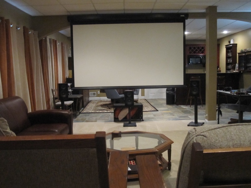
After seeing the picture again I'd say if the screen is down during a measurement: bingo! But I'm guessing it won't be down. Same with the chairs that I interpret as the LP. Where's the microphone positioned?
But I agree you'd want to know what the speaker is doing by itself. And not want to fix something with processing that should or could be fixed elsewhere.
Id rather start with something good and make it better. But I often see the general misconception that processing is a good tool to make a lousy room sound better. It can, to a degree. But in my opinion it could make a good room sound great! But I'll always advise to fix what you can before the DSP. Unless the DSP is part of the mix. Examples from Barleywater and myself.
And even then, you still need a good speaker.
Hardest thing is this solving at a distance. I'm pretty sure the peak we see in the Filtered IR (at about 2 to 3 ms) is the cause of the dip at ~400 Hz. But without actually being in the room it's hard to tell what's causing it. Barleywater said close by wall, but the way I interpret the floor plan, that wall is only close to one speaker, though on the other side something is close too:
After seeing the picture again I'd say if the screen is down during a measurement: bingo! But I'm guessing it won't be down. Same with the chairs that I interpret as the LP. Where's the microphone positioned?
But I agree you'd want to know what the speaker is doing by itself. And not want to fix something with processing that should or could be fixed elsewhere.
Id rather start with something good and make it better. But I often see the general misconception that processing is a good tool to make a lousy room sound better. It can, to a degree. But in my opinion it could make a good room sound great! But I'll always advise to fix what you can before the DSP. Unless the DSP is part of the mix. Examples from Barleywater and myself.
And even then, you still need a good speaker.
Last edited:
Thanks for all the comments. All of these have considered to a large extent before and I have spent the day covering most of them again. I will only give a short summary of the work, but will answer any questions.
All tests here were on the Right main MW driver only. TW and SWs were muted on that channel. The post beside the speaker mentioned is slightly behind the speaker and small relative to the 400Hz dip.
Things ruled out:
> Blocking the Top/Bottom/Left/Right with various absorbent material as pillows and blankets or instead with 24x36" Styrofoam sheets had no significant effect. There was a small improvement when 2 styro sheets was angled like a horn shielding the ceiling and floor. A very big pile of pillows and blankets in the floor bounce position had a some impact but very little in the 400 Hz area.
> The SEAS MW with its box is definitely not a factor in this issue. Previously I switched the original FL and FR to SL and SR when I built 3 identical speakers to fill out the 5 channel system the issue goes with the location, not speaker. The impedance of 3 of the speakers now located in front is attached. Also the SPL is shown for the listening position Vs 20”.
> The chairs at the LP are always slid away to the back of the room and do not influence the measurement.
> The sofa on the left wall is also not a factor and was slid away again for some of these new measurements to confirm that.
> The toe-in was not changed this time, but the position results from previous attempts to improve the sound. I have evaluated; zero toe-in, Toe-in at the LP (maybe 20°) and this current 30° setting. I found no significant influence, but they were left in that final position due to dispersion measurements that shows the ±10° has a little more SPL variability. If the on axis response is smoothed there would be less smoothness across the rest of the field. So this thought directionally follows the logic applied by Earl Geddes. Although, I do realize it is not the same impact as a horn. Attached is the dispersion charts with and without ±11° shows the effect.
> Screen up or down has no impact.
My overall thought is still that this is not a floor or ceiling reflection or speaker problem. I guess it still must be an early reflection however. I still don’t have a clue as to where it may be from as there are no obvious obstructions present.
The FDW did help the analysis and below are some selected charts of SPL and Phase. The 2 traces are mic at listening position and mic at 24". To me they suggested:
> By 5 cycles the phase and SPL suggests that the dip is very well developed. It is fully developed by 8 cycles.
> The rapid phase rotation shows the nulls develop at; 245 375 420 Hz. Similar nulls in the FL occur but at different frequencies in the range and hence my earlier comments about right to left phase differences in the 100-500Hz range causing the phantom center to be somewhat depressed in my system.
> By 16 Cycles the dips have filled as much as they will from late arriving SPL.
I still don’t think there is anything practical to do about this in my current setup. I still would like to understand the mechanism of the 400Hz dip, but have exhausted the ideas. I will thus go back to my original efforts to see if DRC provides any noticeable benefit in sound quality.
Again, Thanks for all the suggestion and comments. I was able to try a few new ideas based own your comments. As was mentioned, it is very difficult to help on something like this from a distance.
Ok, you've been busy, that's for sure. Impedance looks pretty clean though we could argue there's some wiggle around the 400 area. But without a clean speaker reference I'm not going to argue it's that much of a deal. You'd be surprised though, how often something like that does do harm. See the tiny wiggle in my above damped plot? In my final damping solution I made sure that's gone. Took me a week though(!) I only put that up to show a reference. It was my test speaker with same dimensions and only one driver.
I repeated the damping recipe 25x in the real enclosure.
If you want to take a crack at it with DRC I'd say for starters take a 5 cycle window correction but change EPLowerWindow to 8820 as well as EPPFFinalWindow to 8820 in the 5 cycle template (the one in the DRC samples folder, copy it first to have a backup).
That would be a sliding phase correction of 2 cycles at 20 Hz to 5 cycles at 20 kHz.
That should do something at 400 Hz. You can even bring it up to 3 cycles at 20 Hz but it will possibly mess up the FR response somewhat. You don't even have to re-measure, just run the Generate5CyclesTest.bat and load the resultant file into REW (after converting to wav)
Treat as a normal measurement and research what happened. If successful back of the EPLowerWindow and EPPFFinalWindow (both same value) as much as you can, smaller is better here i.m.h.o. but you're letting DRC do what you did by hand in RePhase.
Just clean up the first wave...
Can't promise you a miracle, but it's free to try right? Can't even promise it will sound good. It's out of the scope of DRC but it worked for me, as an experiment.
Examine the spectrogram, GD plot and FR / phase in the test file, using 1, 2, 3 cycles etc, just to get an idea of what it is doing. If you like one enough generate the real correction and listen to it. You can always confirm it by re-measuring with convolution later on.
The tests from DRC (test script) have proven to be very accurate in my own setup.
Don't forget, have fun! Way to late for me now so I have to go...
Don't forget to check these parameters, they might help to get good results:
EPPFFlatType = L
PLType = L or P
PSFilterType = L
ISType = L
EPPFFlatType = L
PLType = L or P
PSFilterType = L
ISType = L
Thanks!
I have done some preliminary work this morning and have new measurements for input to DRC. am soon ready to run some trials.
I have been thinking about your comment on DRC designer. Knowing that I will be running several trials, your comments make me think I should look into that as the interface. You said it was more friendly after getting familiar with it? Your advice?
Only if you're also planning to play with window length, for example 8 cycles at low frequency, 4 cycles at mid and 6 cycles at high frequency.
It doesn't do that much more than the scripts provided by Gmad, except for the sliders to control the windows. But to play with the EPLowerWindow etc. it can't be used. As it is restricted to 1/16 to 1/24 of the MP Lowerwindow as per DRC documentation's recommendation. So in this case: not really necessary.
It doesn't do that much more than the scripts provided by Gmad, except for the sliders to control the windows. But to play with the EPLowerWindow etc. it can't be used. As it is restricted to 1/16 to 1/24 of the MP Lowerwindow as per DRC documentation's recommendation. So in this case: not really necessary.
I anxiously await your results 😉
Further listening sessions for me today showed me it was worth the experiment.
My Filtered IR isn't any better than yours, except that I have managed to get everything below the -20 dB for at least the first 20 ms. I still can't figure out the other dip around 200 Hz. But technically we didn't find a real cure for the 400 Hz either.
Somehow I can relate. In my right channel I have worse results compared to the left one.
In testing I found more than one cue that influenced the results. So it wasn't one identifiable cause but bit's an pieces adding up. Not solvable without big intrusions in our living room. But compared to your results those reflections were kind of late.
I still think we should be able to solve this puzzle. It's such an early reflection that it should be something obvious. And shared between left and right channel.
Don't give up, we'll find a way 😉
I completed my testing with at the DRC setup suggested in Posts 130/131.
General comments:
> The SPL smoothness is excellent; same as my original '5-cycle' DRC run and much better than can be done with PEQ.
> The apparent GD/phase correction at the listening position was very flat. The actual MW GD/phase tries to follow one of room mode Phase flips however making a rapid 360° rotation in the output of the MW.
> There is a notable rise in 3rd order HD at those frequency where the DRC SPL boost is maximized.
> In limited listening my impression was that the tonal balance was slightly improved over my PEQ/rephase setup. I noticed no ill effects due to the aggressive SPL EQ applied or to the GD/phase irregularity. I'm a little surprised as I often see others warn about such aggressive EQ correction. Possibly my substandard hearing is reduces my sensitivity.
> I'm guessing the potential for the phase flip is why the phase correction for DRC was originally limited to >200Hz. GD/phase sensitivity is reportedly more sensitive 500-7k Hz and it may be difficult to get DRC parameters adjusted to avoid following one or more of the misleading phase rotations of the room modes.
> I tried to adjust the DRC parameters to a little to try to make GD/phase improvement, but made no progress. It is clear I still don't have a good enough understanding of the DRC process and its control parameters.
> I would expect much better GD/Phase/Step results from DRC with better settings, better room acoustics, closer listening position. My setup is possibly more problematic than many others.
The selected charts below are with DRC on top of my current PEQ settings.
Listening Position FL and FR SPL Response:

Listening Position FL and FR Step Response:

Listening Position FL and FR Phase Response:

FL MW SPL DRC Vs noDRC at 20" [to show SPL impact of DRC on this driver].

FL MW Step Response at Listening Position and 20".

FL MW Phase Response at Listening Position and 20".

FL MW Group Delay Response at 20".

FL MW Distortion at Listening Position:

General comments:
> The SPL smoothness is excellent; same as my original '5-cycle' DRC run and much better than can be done with PEQ.
> The apparent GD/phase correction at the listening position was very flat. The actual MW GD/phase tries to follow one of room mode Phase flips however making a rapid 360° rotation in the output of the MW.
> There is a notable rise in 3rd order HD at those frequency where the DRC SPL boost is maximized.
> In limited listening my impression was that the tonal balance was slightly improved over my PEQ/rephase setup. I noticed no ill effects due to the aggressive SPL EQ applied or to the GD/phase irregularity. I'm a little surprised as I often see others warn about such aggressive EQ correction. Possibly my substandard hearing is reduces my sensitivity.
> I'm guessing the potential for the phase flip is why the phase correction for DRC was originally limited to >200Hz. GD/phase sensitivity is reportedly more sensitive 500-7k Hz and it may be difficult to get DRC parameters adjusted to avoid following one or more of the misleading phase rotations of the room modes.
> I tried to adjust the DRC parameters to a little to try to make GD/phase improvement, but made no progress. It is clear I still don't have a good enough understanding of the DRC process and its control parameters.
> I would expect much better GD/Phase/Step results from DRC with better settings, better room acoustics, closer listening position. My setup is possibly more problematic than many others.
The selected charts below are with DRC on top of my current PEQ settings.
Listening Position FL and FR SPL Response:
Listening Position FL and FR Step Response:
Listening Position FL and FR Phase Response:
FL MW SPL DRC Vs noDRC at 20" [to show SPL impact of DRC on this driver].
FL MW Step Response at Listening Position and 20".
FL MW Phase Response at Listening Position and 20".
FL MW Group Delay Response at 20".
FL MW Distortion at Listening Position:
Whatever it is at ~400 Hz, it is clear that it is disrupting the FR/Phase.
DRC cannot fix it without causing more distortion there. How does a waterfall look, does it show a ridge there at 400 Hz?
DRC cannot fix it without causing more distortion there. How does a waterfall look, does it show a ridge there at 400 Hz?
The Post 136 Charts above are on the FL Main Speaker. It is closer to a side wall and there is also the end of a couch about 4' away so there are more reflections than with the FR speaker that was measured earlier. It still has a ~400Hz null, but it is not as large as the FR. I don't suppose there is any assurance that the source of that FL null is the same as for the FR as the setup is not symmetrical for width and furnishings, but have considered it might be. Anyway, below are the charts you asked for. They are from the same measurement of the FL in Post 136. Mic at listening position; 170" distant.
As to the distortion at 400Hz shown in Post 136, I have sometimes noticed a small amount of increase in distortion using 5dB of boost with PEQ on my FR speaker at that same frequency. Nothing nearly that large however. I assumed that the increased distortion in that FL chart is just related to the larger boost provided by DRC.
Let me know if you prefer to return to the FR for analysis instead of this FL. It may be a somewhat cleaner case study. I can provide more data on it if that will help and you are motivated. Don't feel any need to try to identify the cause of the null though. I had pretty much given up on it and have just accepted it as a nebulous room effect.


I will probably do more experimentation with DRC to see what is possible. Mine is probably not a typical case. My preference is to retain my PEQ as explained earlier. It is probably not a good objective way to evaluate DRC, but that is what fits into my setup.
My thought has been:
> Reduce the amount of DRC SPL correction applied as I already have some modest PEQ applied and an wary of applying too much in the 100-600 Hz range.
> Apply DRC SPL EQ as minimum phase rather than linear phase? I'm really not sure which is more appropriate now. I am starting to think that it makes more sense to use linear phase for this step.
> Apply DRC phase correction at the last step and find settings that just removes the excess phase rotation of the direct sound as I now do with rePhase. Avoid phase correction that measures well at the listening position, but may follow a false phase rotations due to reflections or room modes. The final phase should measure flat with the mic very near each driver.
I not sure if DRC is suitable to address those objectives. I also don't know if I will ever be able to understand which parameters in DRC to adjusted.
I only mention all this in case you feel DRC is not suited for my particular ideas and system setup, or have any guidance that would be helpful.
As to the distortion at 400Hz shown in Post 136, I have sometimes noticed a small amount of increase in distortion using 5dB of boost with PEQ on my FR speaker at that same frequency. Nothing nearly that large however. I assumed that the increased distortion in that FL chart is just related to the larger boost provided by DRC.
Let me know if you prefer to return to the FR for analysis instead of this FL. It may be a somewhat cleaner case study. I can provide more data on it if that will help and you are motivated. Don't feel any need to try to identify the cause of the null though. I had pretty much given up on it and have just accepted it as a nebulous room effect.
I will probably do more experimentation with DRC to see what is possible. Mine is probably not a typical case. My preference is to retain my PEQ as explained earlier. It is probably not a good objective way to evaluate DRC, but that is what fits into my setup.
My thought has been:
> Reduce the amount of DRC SPL correction applied as I already have some modest PEQ applied and an wary of applying too much in the 100-600 Hz range.
> Apply DRC SPL EQ as minimum phase rather than linear phase? I'm really not sure which is more appropriate now. I am starting to think that it makes more sense to use linear phase for this step.
> Apply DRC phase correction at the last step and find settings that just removes the excess phase rotation of the direct sound as I now do with rePhase. Avoid phase correction that measures well at the listening position, but may follow a false phase rotations due to reflections or room modes. The final phase should measure flat with the mic very near each driver.
I not sure if DRC is suitable to address those objectives. I also don't know if I will ever be able to understand which parameters in DRC to adjusted.
I only mention all this in case you feel DRC is not suited for my particular ideas and system setup, or have any guidance that would be helpful.
`From the graphs posted it is clear that whatever is messing up the direct sound it does it within the first wave build-up. DRC manages to do something useful, but it might be too heavy handed. No clue from me how to best solve it without knowing the true cause. I was fighting similar things but way less prominent. In my case I can clean up the first arrival without disturbing the rest. At 1/24 I do still have traces left of the problem area's though. The STEP shown here:
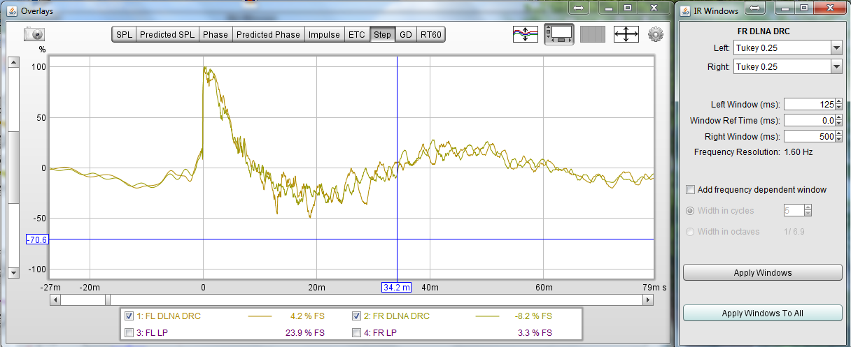
Shows a pretty good clean up by DRC... The question is if it's to heavy handed to listen too and what it does for other positions in the room.
The distortion you got at 400 Hz is something I had at 70 Hz. I know in my case it is a room mode from a corner placed speaker. The other one is free of any irregularities at that frequency. I even tried swapping left and right speaker to confirm. It's the placement causing the dip. So I know I don't want to fill it with DRC. I tried to make my correction short enough to not eliminate it, but still have a remainder of the problem in my signal.
But as it is relatively low in frequency I place a PEQ in the left channel to cut, and fill it in with the right one. Sadly at 400 Hz such things wouldn't work. But as both speakers have a problem there, be it at varying degree it wouldn't be a solution anyway.
The only simple test I can think of is to temporary replace the speaker with a totally different model and test it at the exact same position. See what it does...
That should tell us if it's the position or speaker size/height/etc..
Establish a reference
Hi Jt and everyone,
I dont use any of software under discussion here so I cant offer any specific advice, but I have a good tip that could help.
A couple of posts mention the difficulty of not having a base line or reference measurement for the speakers ie you dont have an anechoic measurement to use as a starter and then "deduct" the room measurement.
The best solution is to take a speaker (or all 3 to allow for build errors / tolerance) to someone who can carry out anechoic measurements....Assuming this is not possible?
If a forum member in the area (high population density in the area?) has a "known quantity" ie well measured speakers, maybe he / she could be persuaded ( expenses plus food and wine!) to bring over a pair of speakers to measure in JT's room and establish a baseline?
Its far from perfect, but would at least go some way to identifying the otherwise unknown room issues.
Hope this helps and all the best
Derek.
- Home
- Loudspeakers
- Full Range
- A convolution based alternative to electrical loudspeaker correction networks