If you make your own valve output stage then you have a great-sounding DAC. One of mine-my own power supplies and tube output stage-sounded as good as a £50k record deck we had it up against on decent recordings
Can you provide a schematic of your output stage?
I'm happy to PM it to anyone interested. I do a build service using this and my own customised psus so don't want to publish it
David
It is very interesting to me. I will be glad if you send them to me. Thank you.
Hello,
I am trying to find a way how to ''integrate '' the Fifopi, Raspberry , some supercaps and the lifepo4 board into my DDDAC chassis.
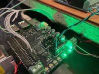
Right there is the small '' ledboard '' connected to wave IO board. The ledboard is attached on a rather big piece of metal together with some smaller stuff. To create more space i wanna remove the metal part to see how much extra space i can create.
Can i just disconnect the flatline and the power cable to this ledboard and keep the wave Io working until it will be '' thrown ''
Greetings, Eduard
I am trying to find a way how to ''integrate '' the Fifopi, Raspberry , some supercaps and the lifepo4 board into my DDDAC chassis.
Right there is the small '' ledboard '' connected to wave IO board. The ledboard is attached on a rather big piece of metal together with some smaller stuff. To create more space i wanna remove the metal part to see how much extra space i can create.
Can i just disconnect the flatline and the power cable to this ledboard and keep the wave Io working until it will be '' thrown ''
Greetings, Eduard
Hello,
Thank you Doede.
Another '' problem '' solved.
Installing the lifepo4, fifopi,raspberry, and 4 ultracap boards can be done BUT if i wanna reduce the I2S cable between Fifopi and DDDAC board somewhere around 10 CM i will probably have to remove one choke from the LCLCLC 12 volt supply to be able to '' approach '' the mainboard a bit better.
I already ordered some UFL cables. On the Fifopi board there is a UFL connector . On the DDDAC mainboard i will just have to connect the 3 central conductor and leave the screen floating.
It will get crowded but the only things giving of some warmth is the LL2771 input choke because the two coils are connected in series ( so 11,2 ohm) and 1A current.
And of course the regulated supply with its choke for the lifepo4 will get a little warm too.
Of course there will be some weight added but that will be ok since since i moved the chassis closer to the ground! Probably can keep it just under 40 kilo.
Greetings, Eduard
Hi Doede.
Back around post #7822 you explained why you feed the WaveIO isolated-side/FiFoPi dirty-side 4V. I think I understand that the LVTTL datasignals coming from the WaveIO was higher than 3.3V when given 5Vcc which the FiFoPi can't handle. Less than 4.6V should be better. Was that about right?
You also stated that you used a separate 12V PSU and a LDOVR regulator here.
Well, it seems that LDOVR's are not readily available at 4V so did you order a custom regulator here, or use something else. I also have a hard time finding any standard 4V LDO's which are not smd.
Sorry for the trivial NOOP electrical question...
Regards...
https://www.diyaudio.com/forums/dig...dac-pcm1794-waveio-usb-input-post6138646.html
Hi Doede.
Back around post #7822 you explained why you feed the WaveIO isolated-side/FiFoPi dirty-side 4V. I think I understand that the LVTTL data signals coming from the WaveIO was higher than 3.3V when given 5Vcc which the FiFoPi can't handle. Less than 4.6V should be better. Was that about right?
You also stated that you used a separate 12V PSU and a LDOVR regulator here.
Well, it seems that LDOVR's are not readily available at 4V so did you order a custom regulator here, or use something else. I also have a hard time finding any standard 4V LDO's which are not smd.
Sorry for the trivial NOOP electrical question...
Regards...
almost, and close enough....
the LVTTL data signals coming from the WaveIO.........
well ...It is more that the FiFoPi is LVTTL compliant. meaning you need to stay below 5 Volt.
The WaveIO outputs whatever level you put as Voltage to the isolator chip. 3,3 / 4 / 5volts / it does not matter
As the FiFoPi does not take anything close or above 5 Volt, I choose a safe level of 4 volts. 4,5 and 3,3 will also work
I just soldered another resistor on the LDOVR, making it 4 Volt
")
Hope that helped?
It did help me understand this particular issue...Thanks!!!
Did you remove and replace a smd-resistor on something like a programmable voltage LDOVR LT3045-S ?
I can't find any detailed information about how to do this on their website...
Hmm, can't figure what to do here. I don't want to compromise the relative clean voltage from a LinearPi psu to the FiFoPi Dirty-side (and ACCUSILICON crystals I guess), and I cannot easily get a 4V regulator (good or not). Anyone with a good suggestion?
no problem !
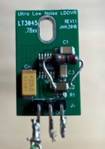
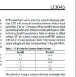
take the datasheet and look at the picture how I did it.... you can take any LDOVR and create a new ref resistor so to speak.
Every 10kOhm is 1 Volt output. So on an existing 5 Volt there should be like 50kOhm. Now just calculate the parallel value and solder a parallel resistor as (at the cap is more space) shown in the image (you know how to do this calculation I presume)
If you have a 3,3 V at hand, you have to remove the ref R of course
Attachments
DDDAC - my story and impressions
Hi all, dear Doede,
even though I have been reading various threads here attentively for several years, this is my first extensive posting in the Diyaudio forum.
The reason for my writing is the DDDAC and the experiences I had with it.
Background
I have been following the DDDAC project for many years, ever since I noticed user reports about NOS Dacs. Prior to the DDDAC, I had already been able to use a converter from Aqua, which, with its filterless NOS design, was already very much in line with my ideas of a hardness-free, smooth analogue sound.
Nevertheless, I have always remained curious about the DDDAC due to the open concept, the flexibility and the wealth of ideas and especially also the personality of Doede Douma. About 2 years ago, the opportunity arose to buy a completely assembled unit. This suited me very well, as I am not really a DIYer: I lack both the technical expertise and the dexterity required at this level - so I am basically dependent on support in these matters.
First impressions
I was immediately taken with the sound of the 4-deck DDDAC, which was equipped with large Miflex capacitors at the time; it was great and intoxicating right from the start. Unfortunately, there was a hum problem right from the start, which I could only solve in a makeshift way. Friendly tips from the forum led me to the idea of replacing the capacitors with output transformers - as it turned out, this was exactly the right way to go.
Unimagined suffering
After I asked Doede directly about it and he explained the alternatives to me, the switch to the Sowter OPT was a foregone conclusion. Doede kindly offered to take a look at the device. I had not expected this, and of course I was delighted! After a careful inspection, he stated that I had probably bought a (quote "Lemon". To cut a long story short: the S11 power supply built into the unit was anything but optimal, it did not deliver what the boards needed. That was a real bummer - at the same time I was incredibly grateful that Doede, of all people, agreed to take care of the matter.
Upgrades
The decision was made to equip the DDDAC with a good power supply in addition to the OPT. And so I finally received the DDDAC back from Doede with the super Sowters plus a Magic Power Supply fully built and checked.
Wow, that was it! Phenomenally good sound: structured, spatial, differentiated, wonderfully timed - at the same time high-resolution and free of any digital harshness - a simply thrilling musical flow. I had never heard it like this from a digital source before - and that's exactly how I always wanted it. A sound experience I like to get really addicted to.
Heartfelt thanks
It's been quite a while now. As a (much too) small thank-you for his tireless, more than friendly and competent support, I had promised Doede a personal report on my experiences, which I am happy to submit now - albeit with considerable delay.
Today, I continue to listen with great satisfaction to the DDDAC. At the same time, I remain open and curious as to what other possibilities may be realised in this great concept.
Further possibilities
In the meantime, further ideas have been incorporated into my device:An eRed dock is now built into the DDDAC as a streamer. It is directly connected via I2S and short signal lines and brings the sound quality of the player to a new level.
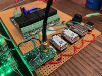
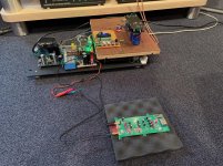
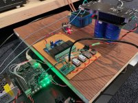
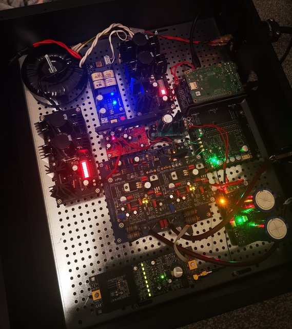
The internal power supply has also been reworked again, both the converter decks and the streaming board have each received their own, completely new linear power supplies and transformers (see snapshots from the construction phase). A friend with a lot of experience in building power supplies took care of the matter. It was really worth it: "blacker backgrounds", a further gain in quietness, space and plasticity in the whole.
Because I was able to optimise the current and clock of my network route last year, which brought unexpected progress for the entire musical reproduction, the next step will be to equip the eRed-Dock streamer in the DDDAC with a better clock.
I am looking forward to further experiences and reports, especially on this exciting topic.
Best regards from Berlin and thanks again to the marvelous Doede
morph
Impressions from the construction phase:

Hi all, dear Doede,
even though I have been reading various threads here attentively for several years, this is my first extensive posting in the Diyaudio forum.
The reason for my writing is the DDDAC and the experiences I had with it.
Background
I have been following the DDDAC project for many years, ever since I noticed user reports about NOS Dacs. Prior to the DDDAC, I had already been able to use a converter from Aqua, which, with its filterless NOS design, was already very much in line with my ideas of a hardness-free, smooth analogue sound.
Nevertheless, I have always remained curious about the DDDAC due to the open concept, the flexibility and the wealth of ideas and especially also the personality of Doede Douma. About 2 years ago, the opportunity arose to buy a completely assembled unit. This suited me very well, as I am not really a DIYer: I lack both the technical expertise and the dexterity required at this level - so I am basically dependent on support in these matters.
First impressions
I was immediately taken with the sound of the 4-deck DDDAC, which was equipped with large Miflex capacitors at the time; it was great and intoxicating right from the start. Unfortunately, there was a hum problem right from the start, which I could only solve in a makeshift way. Friendly tips from the forum led me to the idea of replacing the capacitors with output transformers - as it turned out, this was exactly the right way to go.
Unimagined suffering
After I asked Doede directly about it and he explained the alternatives to me, the switch to the Sowter OPT was a foregone conclusion. Doede kindly offered to take a look at the device. I had not expected this, and of course I was delighted! After a careful inspection, he stated that I had probably bought a (quote
"Lemon". To cut a long story short: the S11 power supply built into the unit was anything but optimal, it did not deliver what the boards needed. That was a real bummer - at the same time I was incredibly grateful that Doede, of all people, agreed to take care of the matter.Upgrades
The decision was made to equip the DDDAC with a good power supply in addition to the OPT. And so I finally received the DDDAC back from Doede with the super Sowters plus a Magic Power Supply fully built and checked.
Wow, that was it! Phenomenally good sound: structured, spatial, differentiated, wonderfully timed - at the same time high-resolution and free of any digital harshness - a simply thrilling musical flow. I had never heard it like this from a digital source before - and that's exactly how I always wanted it. A sound experience I like to get really addicted to.
Heartfelt thanks
It's been quite a while now. As a (much too) small thank-you for his tireless, more than friendly and competent support, I had promised Doede a personal report on my experiences, which I am happy to submit now - albeit with considerable delay.
Today, I continue to listen with great satisfaction to the DDDAC. At the same time, I remain open and curious as to what other possibilities may be realised in this great concept.
Further possibilities
In the meantime, further ideas have been incorporated into my device:An eRed dock is now built into the DDDAC as a streamer. It is directly connected via I2S and short signal lines and brings the sound quality of the player to a new level.
The internal power supply has also been reworked again, both the converter decks and the streaming board have each received their own, completely new linear power supplies and transformers (see snapshots from the construction phase). A friend with a lot of experience in building power supplies took care of the matter. It was really worth it: "blacker backgrounds", a further gain in quietness, space and plasticity in the whole.
Because I was able to optimise the current and clock of my network route last year, which brought unexpected progress for the entire musical reproduction, the next step will be to equip the eRed-Dock streamer in the DDDAC with a better clock.
I am looking forward to further experiences and reports, especially on this exciting topic.
Best regards from Berlin and thanks again to the marvelous Doede
morph
Impressions from the construction phase:


Attachments
Morph - your build looks absolutely sweet!!!!
I have finally got around to building my ultimate (well for now!) integrated DDDAC streamer.
RPI 4 powered by a Salas 5v L-Adapter into Conditionerpi, mounted on a Stationpi with the Fifiopi. DDDAC powered by a Salas L-Adapter through a 12v Sjostrom Super Regulator. Fifopi fed with a Neutron Star clock and a 3.3v UcConditioner.
Everything is supplied properly, all voltages are correct at every point (even checked all voltages from the DAC chips on the top deck) with 2.8v on left and right channels and <0.1v DC offset.
HOWEVER, after using my DDDAC in my previous setup for a number of years I now appear to have significant distortion in both channels. I have tried everything to troublshoot. I have replaced the RPI with the Waveio to see if that works. Changed amplifiers. Measured every measurement I can think of (including the correct resistance at the I/V stage). Could literally moving the DDDAC from one box to another have broken something so badly that I now have extremely loud distortion? It basically sounds like blown speakers in both channels with the actual music very faint in the distance?
Last edited:
Hi Alex,
also great job ! Sad you have this issue....
there is a sequence I always follow. some you probably have done already.
just an idea what to do:
Best thing is always to check all DC and AC specs:
1. Supply voltage 3,3 and 8 Volt at the chips
2. BIAS voltage over Rload (must be like 2,8V)
3. BIAS current pin 20 test point of the DAC (assuming you have the new version) the 40mV test point
4. Are signals arriving at the DAC? (BCK data & FS) use a scope
5. AC signal output at POS and on NEG output versus common (play a 0dBFS 400Hz tone and measure with a DMM AC – must be ~ 1,2V ac)
something of this list must be wrong...
Let me know please !
Good stuff! However, I wonder if the extra wiring and PCB connections degrade the clock signal in some way. So, I was thinking that for your upcoming Accusilicon 318 / 338 comparison you could add another 318 or 338 using some extra-long-and-not-so-great wiring to the comparison, just to see if/how this affects the result in some way. What do you think?
- Home
- Source & Line
- Digital Line Level
- A NOS 192/24 DAC with the PCM1794 (and WaveIO USB input)