Gregg was wheelchair bound and in later years had to use a mouth pointer to type - I don't think any of his speakers went outside for measurements. He did amazing things considering. He may have had some eq on his T15. I think his inroom measurement with the original large vent indicated something he didn't like but I could tell he was having software problems with measurements including impedance. I wonder if the manufacturer would be kind enough to indicate whether the vent in the Metro literature is "close" to what is actually used? - with a test box, it would only take a few minutes to find out.
Freddi,
Are there measurements of T15 anywhere ? I am trying to see if it was actually able to achieve deeper bass extension than K15 given that the volume appears to be about the same maybe smaller. I am working on modeling the T15 in AkAbak and it has been a little slow going and would be helpful to know if I am on the right track.
Are there measurements of T15 anywhere ? I am trying to see if it was actually able to achieve deeper bass extension than K15 given that the volume appears to be about the same maybe smaller. I am working on modeling the T15 in AkAbak and it has been a little slow going and would be helpful to know if I am on the right track.
Sim of Metro T15
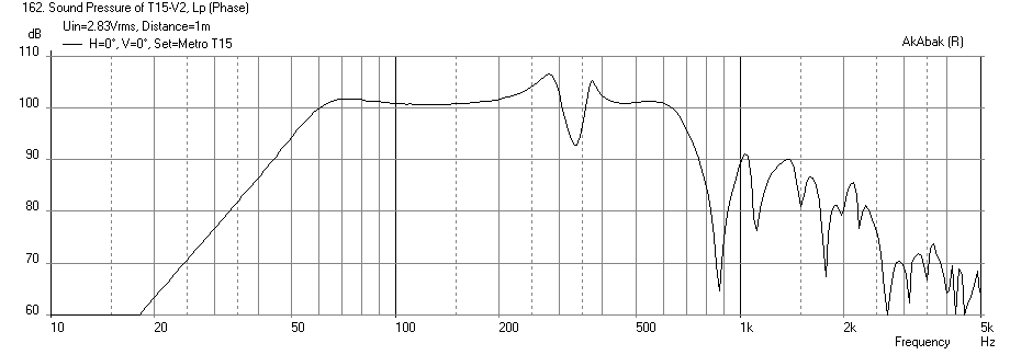
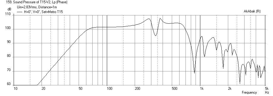
I finally caught a typo in my code and it all seems to work now. Presenting the T15 model - it produces a nice flat bass shelf when used in the open space like a stadium or arena as it was meant for. The bass extension, as I guessed does not appear to go any deeper than a K15 given that the box volume really is about equivalent. There is a 'V' dip - which can become a 'W' shape depending on the exact parameters of the Karlson aperture curve on the front. I am using the same curve function as the K15. The T15 may have a different spec for the curve but that was not given in the drawings. The location of the dip appears to not be at 190 to 270 Hz but my simulation shows that it is from 270 Hz to 370 Hz and the depth is about 6 to 10 dB depending on smoothing. Nonetheless, it appears to be a very nice design suited for kicking butt in large spaces.
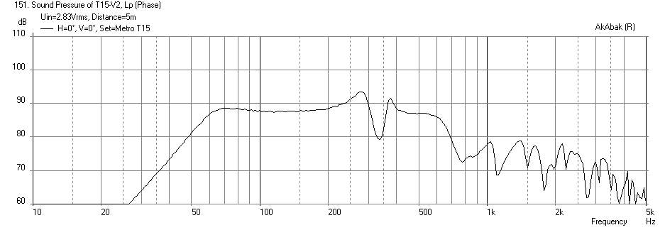
Simulations are with a wall really far away (416 ft to the back - no wall effects) and speaker placed on the floor. I have mic set at driver height above floor (~10 in) and also at a typical seated listener's ear height of 48 in. I have most of the plots for the Eminence Kilomax 15 driver, but also show the Kappa 15A and B&C 15HCX76 at 1 m away and driver height of 10 in for comparisons. They are quite similar but have more SPL at the higher frequencies. The Kilomax being a nominal 95 dB speaker is actually more balanced.
For the Kilomax 15, the SPL at 40 Hz (1 m away) is ony 86 dB, and 94 dB at 50 Hz (not bad)m and about 100 dB otherwise.
Plots are as follows:
- SPL vs Freq of Kilomax 15 at 1 m with 2.83V input, mic at 10 in height
- SPL of Kilomax at 5m away with mic at 48 in height
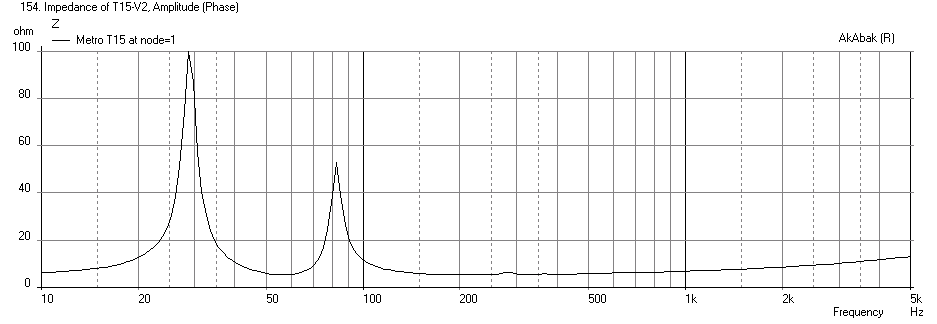
- Impedance of Kilomax 15
- Cone displacement of Kilomax 15

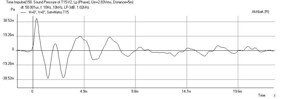
- Impulse response of Kilomax
- SPL vs Freq of Kappa 15A
- SPL vs Freq of B&C 15HCX76
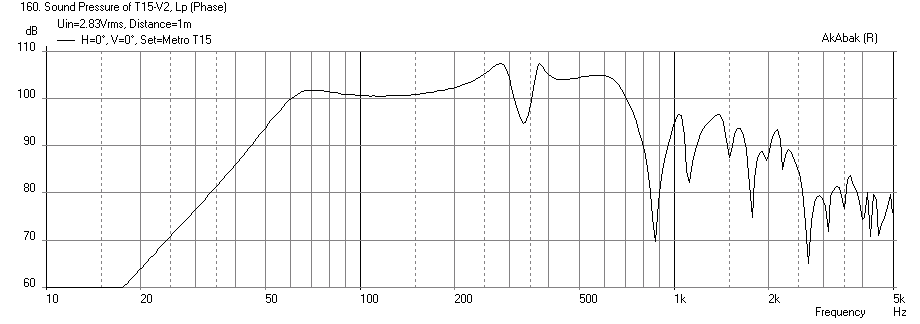
Let me know what you guys think of the simulation and if this model looks like it may actually be similar to what measurements show. I have not yet seen any measurements of the T15 so this is a true "blind" prediction. 😀
I finally caught a typo in my code and it all seems to work now. Presenting the T15 model - it produces a nice flat bass shelf when used in the open space like a stadium or arena as it was meant for. The bass extension, as I guessed does not appear to go any deeper than a K15 given that the box volume really is about equivalent. There is a 'V' dip - which can become a 'W' shape depending on the exact parameters of the Karlson aperture curve on the front. I am using the same curve function as the K15. The T15 may have a different spec for the curve but that was not given in the drawings. The location of the dip appears to not be at 190 to 270 Hz but my simulation shows that it is from 270 Hz to 370 Hz and the depth is about 6 to 10 dB depending on smoothing. Nonetheless, it appears to be a very nice design suited for kicking butt in large spaces.
Simulations are with a wall really far away (416 ft to the back - no wall effects) and speaker placed on the floor. I have mic set at driver height above floor (~10 in) and also at a typical seated listener's ear height of 48 in. I have most of the plots for the Eminence Kilomax 15 driver, but also show the Kappa 15A and B&C 15HCX76 at 1 m away and driver height of 10 in for comparisons. They are quite similar but have more SPL at the higher frequencies. The Kilomax being a nominal 95 dB speaker is actually more balanced.
For the Kilomax 15, the SPL at 40 Hz (1 m away) is ony 86 dB, and 94 dB at 50 Hz (not bad)m and about 100 dB otherwise.
Plots are as follows:
- SPL vs Freq of Kilomax 15 at 1 m with 2.83V input, mic at 10 in height
- SPL of Kilomax at 5m away with mic at 48 in height
- Impedance of Kilomax 15
- Cone displacement of Kilomax 15
- Impulse response of Kilomax
- SPL vs Freq of Kappa 15A
- SPL vs Freq of B&C 15HCX76
Let me know what you guys think of the simulation and if this model looks like it may actually be similar to what measurements show. I have not yet seen any measurements of the T15 so this is a true "blind" prediction. 😀
Attachments
-
 T15-Kilomax15-Freq-1m.png14.1 KB · Views: 607
 -
 T15-Kilomax15-Freq-5m.png13.9 KB · Views: 606
 -
 T15-Kilomax15-Impedance.png12.3 KB · Views: 608
 -
 T15-Kilomax15-Displ.png21 KB · Views: 603
 -
 T15-Kilomax15-Impulse.png12.3 KB · Views: 600
 -
 T15-Kappa15A-Freq-1m.png22.7 KB · Views: 587
 -
 T15-BC15HCX76-Freq-1m.png22.6 KB · Views: 601
Last edited:
hi X -- I think the cone null on T15 and K15 is coming in too high (?) - nearfield on K15 and a K15 sized coupler with 18, for some reason I see a near-cone null about 1/2 octave below fb , or ~37Hz in K15 - what would cause that effect???
here is the PDF covering T15 and its designer gives explanation of this hybrid cabinet and its benefits on distortion reduction and better fidelity (if that matters in pro work)
http://www.metroaudiosystems.gr/pages/manuals/E_Array_Manual_en.pdf
here's T15's 2.83v 1M response from Metro's literature - I'd love to have at least 2 for home use - 2 per side would rock - T18 should work - not so sure about a "T12" ? - what do you think?
my two pairs of B&C are 15PZB40 and 15TBX40
it would be cool to find a picture of a T15 open or an impedance plot
the vent hinted at in Metro's literature has a healthy area
An externally hosted image should be here but it was not working when we last tested it.
here is the PDF covering T15 and its designer gives explanation of this hybrid cabinet and its benefits on distortion reduction and better fidelity (if that matters in pro work)
http://www.metroaudiosystems.gr/pages/manuals/E_Array_Manual_en.pdf
here's T15's 2.83v 1M response from Metro's literature - I'd love to have at least 2 for home use - 2 per side would rock - T18 should work - not so sure about a "T12" ? - what do you think?
my two pairs of B&C are 15PZB40 and 15TBX40
An externally hosted image should be here but it was not working when we last tested it.
it would be cool to find a picture of a T15 open or an impedance plot
the vent hinted at in Metro's literature has a healthy area
An externally hosted image should be here but it was not working when we last tested it.
Last edited:
Freddi, any idea if GregB's struggle to get LF in room related to the room? Do you know if he ever measured outdoors?
I think you are referring to the late Gregg Baker??
Just for clarification: Gregg Baker never went by "Greg B". We are different people... The only handle Gregg ever used (other than his name) was "Eeehaah".
OT - here's something which looks like it would be fun to clone http://www.danleysoundlabs.com/danley/wp-content/uploads/2013/06/BC-412-spec-sheet.pdf
bet this baby kicks pretty well
http://www.danleysoundlabs.com/danley/wp-content/uploads/2013/06/BC415I-ISO-View-White-Horn2.jpg
http://www.diyaudio.com/forums/subwoofers/229627-bc412-subwoofer.html
bet this baby kicks pretty well
http://www.danleysoundlabs.com/danley/wp-content/uploads/2013/06/BC415I-ISO-View-White-Horn2.jpg
http://www.diyaudio.com/forums/subwoofers/229627-bc412-subwoofer.html
Last edited:
OT - here's something which looks like it would be fun to clone http://www.danleysoundlabs.com/danley/wp-content/uploads/2013/06/BC-412-spec-sheet.pdf
bet this baby kicks pretty well
http://www.danleysoundlabs.com/danley/wp-content/uploads/2013/06/BC415I-ISO-View-White-Horn2.jpg
http://www.diyaudio.com/forums/subwoofers/229627-bc412-subwoofer.html
Something of a hippo at 277 pounds (125kg). FR towards LF shows it edging down a bit just after 50Hz and committing to decline at 45Hz. Looks like a 12dB/oct rolloff towards 20Hz. That's probably a very natural sounding/feeling ratio.
Last edited:
Tip of a large brim hat to Xrk! I'm still meditating on what sort of esoteric offering I should make 😀
Decisions decisions... The commercial Metro T15 FR shows bass falling steeply ~23dB from 50 to 30Hz while X's akabak model shows a slower and more linear decline. Is this marketing in action (MIA) <or> is X's great Akabak model missing something <or> is the vent size on the real T15 smaller as per Gregg Bakers discovery?
Freddi, does a smaller vent result in less HF boost as per the Metro Graph?
& Another question, since the Karlson alignment reduces excursion below Fb how does it respond to EQ? I don't have an issue with a +6dB bump below 50 if I know the alignment is going to keep cone excursion down. If/Since the K has amazing cone control (1/5th comparable bass reflex?) then it gives us room to do what no other alignment dare do?
Any thoughts on EQ'ng these in a PA setting? The flat shelf with only one notch up to 500hz and probable reduction in cabinet-verb by folded path, the simulated T15's looking pretty sweet.
Last edited:
the Metro had a PHL woofer - I think Gregg got the cabinet and aperture about right - he may have undersized the vent due either to a room mode or interpretation of a bad graph -?? - a test cabinet would need to be made - or make a neat means to change the vent that Gregg dimensioned from Metro's sketch. T15 is a nice size like THAM 15 and Jim Bell's single sheet tapped horn. I might ask Metro if the drawing is about correct. That vent has to clear the woofer.
you can see Metro's graph was losing signal to noise ratio at the 2.83v drive - 20 watts would have made it easier to figure - if it really does 40 (2pi?) at -3 to - 6dB then that's pretty solid bass. The little X15 with a light cone woofer rolls off quite high.
a T15 clone would be cool with a little Karlson http://www.youtube.com/watch?v=yWnKpr4coPE
Last edited:
I'm very interested in this design and will make a test cab. Only difficulty is time. Could start on it in a couple weeks.
Freddi, Any thoughts about LF excursion and EQ or vent size in K15's affecting bass vs treble balance.. I've read nearly all you're posts around the net except for the offline gainclone forum. I'm sure you'd just be repeating something, still, keeping all the facts, evidences and myths straight has been difficult.
Freddi, Any thoughts about LF excursion and EQ or vent size in K15's affecting bass vs treble balance.. I've read nearly all you're posts around the net except for the offline gainclone forum. I'm sure you'd just be repeating something, still, keeping all the facts, evidences and myths straight has been difficult.
Right, I was just comparing it the THAM 15. I think T15 is a bit smaller. IIRC 3 linear inches less. Not sure about weight... I would expect it to be much lighter given the THAM's folds and bracing.
Anthony and Freddi,
Thanks for the feedback. I am a little bummed that my sim doesn't show the bass shelf extension down to 50 Hz like the Metro measurement. Seeing the ripple in the response provided by Metro I would have to say it was done in a room because when I add a wall at about 5 ft in the back of the T15 I get similar ripples and dips. So I wonder if the 95dB response at 40 Hz is partially a room enhanced mode or is it really the speaker? The other thing I can't figure out is why my notch is that far off. I will take a look at my code again and double check the dimensions. AkAbak usually gets these things much closer if the dimensions are correct. So my question is the drawing from the YouTube video (Gregg Baker's I presume) close to what a T15 that was measured by Metro in the freq response plot shown above?
Thanks for the feedback. I am a little bummed that my sim doesn't show the bass shelf extension down to 50 Hz like the Metro measurement. Seeing the ripple in the response provided by Metro I would have to say it was done in a room because when I add a wall at about 5 ft in the back of the T15 I get similar ripples and dips. So I wonder if the 95dB response at 40 Hz is partially a room enhanced mode or is it really the speaker? The other thing I can't figure out is why my notch is that far off. I will take a look at my code again and double check the dimensions. AkAbak usually gets these things much closer if the dimensions are correct. So my question is the drawing from the YouTube video (Gregg Baker's I presume) close to what a T15 that was measured by Metro in the freq response plot shown above?
I'm very interested in this design and will make a test cab. Only difficulty is time. Could start on it in a couple weeks.
Freddi, Any thoughts about LF excursion and EQ or vent size in K15's affecting bass vs treble balance.. I've read nearly all you're posts around the net except for the offline gainclone forum. I'm sure you'd just be repeating something, still, keeping all the facts, evidences and myths straight has been difficult.
Anthony,
The sim predicts about 0.75 mm cone excursion at 40 Hz with 2.83v input. This is about 3x more displacement than the peak near 60 Hz. So within the main bandpass the cone excursion is very small and well controlled. If you EQ down at 40 Hz you may get away with it if you use something like a Beyma http://profesional.beyma.com/pdf/15P80NdE.pdf which has like 52 mm of stroke before physical damage occurs.
Tell me how much power you want run through these (or volts) and I can tell you what the max cone excursion is. That will tell you how much EQ you can apply.
Last edited:
K15's vent varied from 40sq.in. (1954) to 30.5 sq.in. (1956 "changeover mod) - from what I've observed, that change mainly affects the response in the 200 to 350 or so region and the changeover could have been picked subjectively. K15 is a wonderful speaker and might be "improved upon a bit" - its already better than many designs and a classic. Deletion of the front shelf would allow more HF to bounce into the upper part of the coupler.
the baffle tilt of a K can affect the graph a bit- T15 could probably sound pretty well balanced as a 2-way but was intended as a woofer to augment Metro's line array
look at the following graphs of a Karlsonette copy where I blocked the main horizontal vent and hacked a small rectangular vent in the top of its port board vs an Acoustic Control 115BK which seems based upon the Transylvania Power Company K-coupler. 115BK had a 27 sq. in. vent and size wise probably descended directly from Karlson's 1965 X15 system which employed a 15" woofer and K-coupler tweeter. The first K-coupler tweeter in the X15 was a wooden klam-type driven by a 3" cone speaker -then it progressed to a slotted pipe with compression driver. If I were able to make good cabinets then I would attempt a K15 bulk 2-way with an internal K-tube.
both of these graphs were at the mic on the ground perspective -
- the front geometry along with vent area along with rear geometry seem to influence how smooth they play. There was no damping material whatsoever in the 115BK cabinet. 115BK without the wing inset would be 20.5" wide by 27" tall by 13.5" deep. I would like to see a simulation of it scaled to K15 bulk.
does T15 with its "foldback" section behave like a "high aspect Karlson"?
the little K12 sounded ok but the steady state suckout looked bad - PYM1298 was an Eminence built Pyle similar to their Kappa12A - whether a little K goes "low" - ha - drumkit at 200 watt input peaks is a lot of fun. For home use, a 5.3" long K-tube on a compression driver will sound great on hi-hat and other cymbals
115BK internal dimensions - the wings are radial arc - the vent is centered in the upper "reflector" board (ain't much area to :"reflect" -
http://img490.imageshack.us/img490/5278/115bksidekp5.jpg
the baffle tilt of a K can affect the graph a bit- T15 could probably sound pretty well balanced as a 2-way but was intended as a woofer to augment Metro's line array
look at the following graphs of a Karlsonette copy where I blocked the main horizontal vent and hacked a small rectangular vent in the top of its port board vs an Acoustic Control 115BK which seems based upon the Transylvania Power Company K-coupler. 115BK had a 27 sq. in. vent and size wise probably descended directly from Karlson's 1965 X15 system which employed a 15" woofer and K-coupler tweeter. The first K-coupler tweeter in the X15 was a wooden klam-type driven by a 3" cone speaker -then it progressed to a slotted pipe with compression driver. If I were able to make good cabinets then I would attempt a K15 bulk 2-way with an internal K-tube.
both of these graphs were at the mic on the ground perspective -
- the front geometry along with vent area along with rear geometry seem to influence how smooth they play. There was no damping material whatsoever in the 115BK cabinet. 115BK without the wing inset would be 20.5" wide by 27" tall by 13.5" deep. I would like to see a simulation of it scaled to K15 bulk.
does T15 with its "foldback" section behave like a "high aspect Karlson"?
the little K12 sounded ok but the steady state suckout looked bad - PYM1298 was an Eminence built Pyle similar to their Kappa12A - whether a little K goes "low" - ha - drumkit at 200 watt input peaks is a lot of fun. For home use, a 5.3" long K-tube on a compression driver will sound great on hi-hat and other cymbals
An externally hosted image should be here but it was not working when we last tested it.
An externally hosted image should be here but it was not working when we last tested it.
115BK internal dimensions - the wings are radial arc - the vent is centered in the upper "reflector" board (ain't much area to :"reflect" -
http://img490.imageshack.us/img490/5278/115bksidekp5.jpg
Last edited:
assuming T15's 2pi cutoff is similar to X's simulation - that's still an octave better than a 10 cubic foot W-bin such as my Peavey FH1 which is similar to a Klipsch Belle only 6 inches deeper
at higher levels and indoors, the FH1 is reasonably listenable and of course like a La Scala but braced better. It does little good to have LF extension if a speaker is overtaxed so even a LS type will do better than most FR with demanding material such as Dan Weiss "Tintal" (tabla raga transcribed to western drumkit - drone instrument = a Stratocaster vs traditional harmonium)
at higher levels and indoors, the FH1 is reasonably listenable and of course like a La Scala but braced better. It does little good to have LF extension if a speaker is overtaxed so even a LS type will do better than most FR with demanding material such as Dan Weiss "Tintal" (tabla raga transcribed to western drumkit - drone instrument = a Stratocaster vs traditional harmonium)
An externally hosted image should be here but it was not working when we last tested it.
Freddi,
What does an FH1 look like internally? The K15 is a very nice time tested design and according to my sim, the T15 is not better, maybe more compact but performance wise I am guessing about the same. Maybe even a little less efficient.
What does an FH1 look like internally? The K15 is a very nice time tested design and according to my sim, the T15 is not better, maybe more compact but performance wise I am guessing about the same. Maybe even a little less efficient.
FH1 was a bifurcated "W" midbass horn much like the Klipsch La Scala and PWK's "Belle" (which was a "flattened" domestic version of La Scala)
Belle plan (the V things in the mouth are the grilles) - FH1 had about the same frontal dimnesions as a Belle but at 24" depth was 6" deeper than a Belle. A Belle type could be made from one 4'by 8' sheet. DJK (Dennis Kleitsch) came up with a way to convert La Scala to a vented hybrid by using the upper horn chamber as a volume extension of the back chamber.
http://forums.klipsch.com/forums/storage/3/1009906/Belle_LATEST.pdf
Karlson subjective performance can be influenced by aperture changes, reflector changes, vent changes - K15 with a good coaxial is imo an excellent and musical performer. I could have saved a lot by sticking with the Klipschorn as its horrible on harpsichord -(bought 100 harpsichord cds) hahaha
the apple of my old-school horn eye was the University Classic but a recent sim by RCA-Fan indicated that his tiny hypex horn with a 12PE32 might play smoother and better. K-builder Carl has built 4- of the University Classic for a musician relative - - says K15 can keep up with the Classic.
http://www.hifilit.com/hifilit/University/plans-1.jpg
T15 doesn't have a lot of total internal airspace - Gregg said it would play stronger than what his neighbors could tolerate - it looks awkward to lift but could be fun in a K-based home system
Last edited:
The only advantage I can see of FH1 is less phase anomalies in the response above the Karlson notch making a 1k or greater crossover comfortable for people who are bothered by a little bit of cabinet color...
Besides being a bear to move (many owners of PA's have said as much) the FH1 doesn't offer much below 70Hz. It's falling like a rock pretty early on.
After researching subs and horns for a couple years (besides performing on a fair number of PAs most years) the T15 is looking promising, I'm considering the possibility of eating a few inches to move Fb a bit lower (is that done by a larger back chamber or a longer path from front to back or both?)... Even if 3 inches bigger, It'll still be lighter, smaller and more extended into MF than the competing tapped horns. Before I go experimenting though I plan to build the design you simulated so we can see how your model is working.
Last edited:
K15 was intended for coaxial or fullrange and sounds excellent that way - K15 will blend reasonably well with some horns - I had really nice sound with a SFW radial horn ~30" wide and 28" deep as a midhorn and also the old Smith Distributed Source Horn as a two way. A K-tube on top of a bass coupler will work even if the coupler is 4 foot tall. Its also good to internally mount a K-tube.
here's a low res cheap camera pic of my SFW horn on top of K15 - it made an interesting "big tweeter" crossed-overed around 1K5

I'd like to know it the 115BK will directly scale. As is, a little (27"x20.5 x 13.5) 115Bk topped with a K-tube is a lot of fun and quite realistic on a drumkit and its cymbals.
here's a low res cheap camera pic of my SFW horn on top of K15 - it made an interesting "big tweeter" crossed-overed around 1K5
I'd like to know it the 115BK will directly scale. As is, a little (27"x20.5 x 13.5) 115Bk topped with a K-tube is a lot of fun and quite realistic on a drumkit and its cymbals.
An externally hosted image should be here but it was not working when we last tested it.
Last edited:
- Home
- Loudspeakers
- Full Range
- A Speaker that Kicks Butt in Large Spaces