Oh now – that’s no good if they are prone to loosen grip and release under vibration. Using adhesive once the mounting disc is finally fixed to the panel makes sense but negates the whole objective of easily replacing a faulty exciter. So, these mounting discs are great for experimenting with different positions and even multiple exciters on a panel, but why on earth are they sold in packs of 5? Surely an even number in the world of stereo makes more sense?
Am I correct in thinking that this new EX series is simply a few of the popular DAEX exciters in a different jacket?
Am I correct in thinking that this new EX series is simply a few of the popular DAEX exciters in a different jacket?

Hello,Oh now – that’s no good if they are prone to loosen grip and release under vibration. Using adhesive once the mounting disc is finally fixed to the panel makes sense but negates the whole objective of easily replacing a faulty exciter. So, these mounting discs are great for experimenting with different positions and even multiple exciters on a panel, but why on earth are they sold in packs of 5? Surely an even number in the world of stereo makes more sense?
Am I correct in thinking that this new EX series is simply a few of the popular DAEX exciters in a different jacket?
Let me add 2 aspects:
- Academic papers about DML predict a HF roll off between the voice coil mass and the panel mechanical impedance. My experiments shown the roll off with important mass (8g). For lower mass not so obvious (the results are somewhere in posts of this thread). For now, I would stay cautious about extra mass.
- Another possible HF roll off is due to the reduction of the mechanical force that drives the panel because of the reduction of the current( ask to M Laplace : F = BLi) because of the inductance and the constant voltage drive from the amplifier. Having an 8 ohm driver will increase the roll off frequency for a given inductance.
Christian
Essentially yes they are existing exciters with a revised connection method. In principle it’s a good idea but they may have got their thread design wrong. Please note I have only had one experience of this happening so it may be a manufacturing tolerance issue. Time will tell.Oh now – that’s no good if they are prone to loosen grip and release under vibration. Using adhesive once the mounting disc is finally fixed to the panel makes sense but negates the whole objective of easily replacing a faulty exciter. So, these mounting discs are great for experimenting with different positions and even multiple exciters on a panel, but why on earth are they sold in packs of 5? Surely an even number in the world of stereo makes more sense?
Am I correct in thinking that this new EX series is simply a few of the popular DAEX exciters in a different jacket?
Burnt
Perfect Impulse
Commercial exciters need to be affordable in order to sell and so cost will define the performance of exciters to a large degree. If you pay $30 for an exciter taxation, distribution costs, retailer profit all reduce the cost available to the manufacturer for the component. DIY is free of all of those constraints so what might a clean sheet of paper design for an exciter look like if we removed cost constraints?
I have captured my initial thoughts below, but I would be very interested in any observations you might wish to make.
What are the areas of exciter design that may benefit?
Some possible routes to investigate. Two exotic options first.
Practicalities.
Both speaker motor magnets and voice-coils can be bought online and motor cases and spiders can be printed using a 3D printer ( including carbon fibre filled materials) so experimentation is feasible, although it remains technically challenging. The biggest hurdles that I can see are more in the area of the motor design itself, simulating the magnetic circuit is a non-trivial exercise and measuring the results of each new design will be a challenge. However, all designs start off on a bench top somewhere so there must be a way. Also, some of the options can be tested by adapting existing exciters.
As usual all the above are shared with the DIY community under the copyleft principle used by the open source community. Anyone in the community is free to use the ideas discussed above and adapt them as they see fit. A small plea to the manufacturers that contribute to this website, please respect the copyleft principle and don’t be evil. Karma always wins in the end.
Burnt.
Commercial exciters need to be affordable in order to sell and so cost will define the performance of exciters to a large degree. If you pay $30 for an exciter taxation, distribution costs, retailer profit all reduce the cost available to the manufacturer for the component. DIY is free of all of those constraints so what might a clean sheet of paper design for an exciter look like if we removed cost constraints?
I have captured my initial thoughts below, but I would be very interested in any observations you might wish to make.
What are the areas of exciter design that may benefit?
- Panel/exciter interface- can we do better than double sided tape? Can we get a benefit by increasing the attachment area to increase adhesion, or is decreasing the attachment area as a force concentrator a better way to go?
- Voice coil design- 25mm diameter voice coils seem to suffer from less buckling strain than 32mm voice coils. But 25mm coils offer less coil length ( the L in F=BLI) and so, all other things being equal, less motor force. Can we either use better materials for 32mm coil formers- e.g Carbon fibre or Aluminium, or can we compensate for 25mm diameter coils reduced L by increasing B, the magnetising flux, or increasing I, the current delivered?
- Suspension design. From what I can see this part of exciter design has received a lot of focus and performs quite well, however there is plenty of evidence of noise from some metal suspensions. To gain a performance enhancement perhaps we rethink this area completely?
- Regarding the motor force F= BLI, current, the I in the motor force equation, is supplied by the user. For the manufacturer current is free, so it makes sense for the manufacturer to bias their motor design towards being a current user and, for a given F, reduce the magnet and amount of wide in the voice coil as these are a direct cost to the manufacturer. We can gain efficiency if we increase magnetic field intensity B and voice coil length L
- Demonstrating that all design is a mater of balancing opposing constraints, increasing L increases the inductance of the voice coil which rolls off the HF response. Can we improve HF response by reducing L and increasing B to compensate for the loss in efficiency?
- Newton tells us every force has an equal and opposite reaction. We usually absorb the reaction by mounting the exciter to a spline, or let the exciter mass provide a reaction mass which in my experience only works well at low to mid volume or where we limit the bandwidth of the exciter to omit bass frequencies. . Is it possible to harness the reaction force to drive a second panel?
- Exciters need to be shipped worldwide and mass is expensive to ship. Freed from this constraint can we gain performance improvements by using heavier materials, e.g. metal instead of plastic for the body?
- There are a lot elements in the panel/exciter system. Voice coil, voice coil suspension/spider, and sometimes two of them, voice coil drive plate, suspension frame or basket, the panel itself, which makes for a complex system. Each component alone is a potential source of distortion and there will be secondary effects cause by the interactions between the different components. Can we eliminate some components to simplify the system?
- Can we improve the performance by using techniques new to exciter design e.g. the use of ferrofluid may improve heat transfer from the voicemail and potentially damp any unwanted voicemail resonances?
- At this time I don’t know if the motor design uses a long coil/short magnet gap approach, but I suspect they probably do because magnets are much more expensive than copper wire so the manufacturer would want to reduce this cost. Displacement is not an issue for exciters as they are designed to impart an impulse to the panel to propagate surface waves rather than move the panels in a piston like mode, and so a short stroke for the voice coil is a given. But it is just possible that with such cheap components made in the millions there may be compromises here as well that could be removed. A long magnetising gap and short coil may offer a better balance?
Some possible routes to investigate. Two exotic options first.
- Mounting the voice coil directly to the panel would eliminate the voice coil former which removes buckling strain noted in 2. above, removes the drive plate and provide a very stiff coupling between panel and voice coil. This would be a less efficient motor design than the conventional one and require a significantly stronger magnetic field to compensate.
- Assuming a more conventional exciter design, can we provide a rear mount to allow a second panel to be attached to and driven by the exciter. This second panel could be of a size, shape, and material to extend, or augment the main panel. I note that a second full size panel would introduce interesting challenges, e.g. the gap between the two panels produced by a typical exciter would reduce the size of the wave form than can form between the two panels , i.e., the output would be bandwidth constrained.
- Tapering the size of the drive plate to reduce the contact area could provide a force concentrator to improve the transmission of signal to the panel?
- Freed of the cost constraints we can certainly revisit the balance of magnet size, voice coil length and current that F=BLI requires, e.g. a bigger magnet and smaller coil to improve HF response for a given force
- Freed of the cost constraints we can consider stiffer materials for the voice coil former to reduce/eliminate voice coil buckling.
Practicalities.
Both speaker motor magnets and voice-coils can be bought online and motor cases and spiders can be printed using a 3D printer ( including carbon fibre filled materials) so experimentation is feasible, although it remains technically challenging. The biggest hurdles that I can see are more in the area of the motor design itself, simulating the magnetic circuit is a non-trivial exercise and measuring the results of each new design will be a challenge. However, all designs start off on a bench top somewhere so there must be a way. Also, some of the options can be tested by adapting existing exciters.
As usual all the above are shared with the DIY community under the copyleft principle used by the open source community. Anyone in the community is free to use the ideas discussed above and adapt them as they see fit. A small plea to the manufacturers that contribute to this website, please respect the copyleft principle and don’t be evil. Karma always wins in the end.
Burnt.
according to what is the best way to stably attack the exciters? I was thinking of using the resin or maybe continuing with the adhesive but sooner or later it loses its adhesion. I would also like to make a case on a kind of frame with back support to hold the exciters. Some idea?
Hi BurntPerfect Impulse
Commercial exciters need to be affordable in order to sell and so cost will define the performance of exciters to a large degree. If you pay $30 for an exciter taxation, distribution costs, retailer profit all reduce the cost available to the manufacturer for the component. DIY is free of all of those constraints so what might a clean sheet of paper design for an exciter look like if we removed cost constraints?
I have captured my initial thoughts below, but I would be very interested in any observations you might wish to make.
What are the areas of exciter design that may benefit?
- Panel/exciter interface- can we do better than double sided tape? Can we get a benefit by increasing the attachment area to increase adhesion, or is decreasing the attachment area as a force concentrator a better way to go?
- Voice coil design- 25mm diameter voice coils seem to suffer from less buckling strain than 32mm voice coils. But 25mm coils offer less coil length ( the L in F=BLI) and so, all other things being equal, less motor force. Can we either use better materials for 32mm coil formers- e.g Carbon fibre or Aluminium, or can we compensate for 25mm diameter coils reduced L by increasing B, the magnetising flux, or increasing I, the current delivered?
- Suspension design. From what I can see this part of exciter design has received a lot of focus and performs quite well, however there is plenty of evidence of noise from some metal suspensions. To gain a performance enhancement perhaps we rethink this area completely?
- Regarding the motor force F= BLI, current, the I in the motor force equation, is supplied by the user. For the manufacturer current is free, so it makes sense for the manufacturer to bias their motor design towards being a current user and, for a given F, reduce the magnet and amount of wide in the voice coil as these are a direct cost to the manufacturer. We can gain efficiency if we increase magnetic field intensity B and voice coil length L
- Demonstrating that all design is a mater of balancing opposing constraints, increasing L increases the inductance of the voice coil which rolls off the HF response. Can we improve HF response by reducing L and increasing B to compensate for the loss in efficiency?
- Newton tells us every force has an equal and opposite reaction. We usually absorb the reaction by mounting the exciter to a spline, or let the exciter mass provide a reaction mass which in my experience only works well at low to mid volume or where we limit the bandwidth of the exciter to omit bass frequencies. . Is it possible to harness the reaction force to drive a second panel?
- Exciters need to be shipped worldwide and mass is expensive to ship. Freed from this constraint can we gain performance improvements by using heavier materials, e.g. metal instead of plastic for the body?
- There are a lot elements in the panel/exciter system. Voice coil, voice coil suspension/spider, and sometimes two of them, voice coil drive plate, suspension frame or basket, the panel itself, which makes for a complex system. Each component alone is a potential source of distortion and there will be secondary effects cause by the interactions between the different components. Can we eliminate some components to simplify the system?
- Can we improve the performance by using techniques new to exciter design e.g. the use of ferrofluid may improve heat transfer from the voicemail and potentially damp any unwanted voicemail resonances?
- At this time I don’t know if the motor design uses a long coil/short magnet gap approach, but I suspect they probably do because magnets are much more expensive than copper wire so the manufacturer would want to reduce this cost. Displacement is not an issue for exciters as they are designed to impart an impulse to the panel to propagate surface waves rather than move the panels in a piston like mode, and so a short stroke for the voice coil is a given. But it is just possible that with such cheap components made in the millions there may be compromises here as well that could be removed. A long magnetising gap and short coil may offer a better balance?
Some possible routes to investigate. Two exotic options first.
- Mounting the voice coil directly to the panel would eliminate the voice coil former which removes buckling strain noted in 2. above, removes the drive plate and provide a very stiff coupling between panel and voice coil. This would be a less efficient motor design than the conventional one and require a significantly stronger magnetic field to compensate.
- Assuming a more conventional exciter design, can we provide a rear mount to allow a second panel to be attached to and driven by the exciter. This second panel could be of a size, shape, and material to extend, or augment the main panel. I note that a second full size panel would introduce interesting challenges, e.g. the gap between the two panels produced by a typical exciter would reduce the size of the wave form than can form between the two panels , i.e., the output would be bandwidth constrained.
- Tapering the size of the drive plate to reduce the contact area could provide a force concentrator to improve the transmission of signal to the panel?
- Freed of the cost constraints we can certainly revisit the balance of magnet size, voice coil length and current that F=BLI requires, e.g. a bigger magnet and smaller coil to improve HF response for a given force
- Freed of the cost constraints we can consider stiffer materials for the voice coil former to reduce/eliminate voice coil buckling.
Practicalities.
Both speaker motor magnets and voice-coils can be bought online and motor cases and spiders can be printed using a 3D printer ( including carbon fibre filled materials) so experimentation is feasible, although it remains technically challenging. The biggest hurdles that I can see are more in the area of the motor design itself, simulating the magnetic circuit is a non-trivial exercise and measuring the results of each new design will be a challenge. However, all designs start off on a bench top somewhere so there must be a way. Also, some of the options can be tested by adapting existing exciters.
As usual all the above are shared with the DIY community under the copyleft principle used by the open source community. Anyone in the community is free to use the ideas discussed above and adapt them as they see fit. A small plea to the manufacturers that contribute to this website, please respect the copyleft principle and don’t be evil. Karma always wins in the end.
Burnt.
My answer to quite a few of your criteria is

Cheers 👍
Eucy
😊 I know, but what if you could make it better?
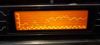
Hopefully if the pics are in the right order, the first two are of another CD with a small fabric dome.
As an experiment, This dome does not have any pva coating .
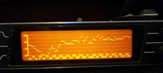
The third picture is the measurements of another CD with the small dome plus pva coating .
It goes down to 250hz.
The fourth pic is the small pva dome CD with me holding the CD in my hands to mimic a firm mounting.
This goes down to 160hz.
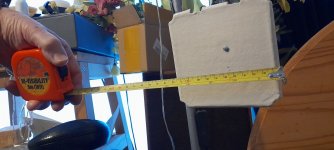
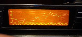
The fifth pic is an old painted paper mache egg box top ,about 5.5 inches in size, that I had left in a draw, unmounted.
The last pic is its frequency response, which goes down to 250hz unmounted.
Although it's turned more into being about domes , the lower frequencies are interesting.
Steve.
As an experiment, This dome does not have any pva coating .
The third picture is the measurements of another CD with the small dome plus pva coating .
It goes down to 250hz.
The fourth pic is the small pva dome CD with me holding the CD in my hands to mimic a firm mounting.
This goes down to 160hz.
The fifth pic is an old painted paper mache egg box top ,about 5.5 inches in size, that I had left in a draw, unmounted.
The last pic is its frequency response, which goes down to 250hz unmounted.
Although it's turned more into being about domes , the lower frequencies are interesting.
Steve.
Attachments


Here they are developing new drives for panel acoustics:Некоторые возможные маршруты для исследования
http://www.tornadoacoustics.ru/forum/24-1117-97 There is an english version.
I've been away from the forum for a long time, so don't know if anyone had posted this link to videos by a guy named Ben. https://www.youtube.com/c/TypicalBenYT/videos
Maybe, one should start checking up his experimenting from the first one, that is a pair of Bamboo panels.
Maybe, one should start checking up his experimenting from the first one, that is a pair of Bamboo panels.
What.!.. Really? No EucyDome Steve??? 😜Hopefully if the pics are in the right order, the first two are of another CD with a small fabric dome.
As an experiment, This dome does not have any pva coating .
The third picture is the measurements of another CD with the small dome plus pva coating .
It goes down to 250hz.
The fourth pic is the small pva dome CD with me holding the CD in my hands to mimic a firm mounting.
This goes down to 160hz.
The fifth pic is an old painted paper mache egg box top ,about 5.5 inches in size, that I had left in a draw, unmounted.
The last pic is its frequency response, which goes down to 250hz unmounted.
Although it's turned more into being about domes , the lower frequencies are interesting.
Steve.
The bamboo laserply didn't work well it seemsI've been away from the forum for a long time, so don't know if anyone had posted this link to videos by a guy named Ben. https://www.youtube.com/c/TypicalBenYT/videos
Maybe, one should start checking up his experimenting from the first one, that is a pair of Bamboo panels.
I tested a sample at it was very 'dead' sounding
Poplar is a better choice imo
Things have moved on from hanging panels though (again imo)
Eucy
Hello Burnt,Perfect Impulse
I have captured my initial thoughts below, but I would be very interested in any observations you might wish to make.
What are the areas of exciter design that may benefit?
Burnt.
- Panel/exciter interface- can we do better than double sided tape? Can we get a benefit by increasing the attachment area to increase adhesion, or is decreasing the attachment area as a force concentrator a better way to go?
This the beginning of a full functional analysis!
I had the possibility to make some tests this week. One of the target was to measure the effect of a coupling part. As you will see, it is not full conclusive on that point but interesting on another (at least to my point of view) and related to your list.
Here is a picture of the tested panels.
All the panels are 20x30cm XPS 9mm (depron)... I had a stock of this. In fact it is the second material I made panels which have never worked and I would like to understand why...
Left is a concentrator made of wood sticks, central is a bottom of soda can (44mm) to enlarge the contact diameter with the panel. Both are on the exciter side. Right is an Eucy's dome so in front of the panel.
Red is panel without accessory, green the concentrator (left on the picture above)
Red, the panel without accessory, blue with the 44mm dome as coupler
Red, the panel without accessory, orange with an Eucy's dome
What I understand from this test is the sensitivity of light membrane to additional mass - in better words, low mechanical impedance material.
Higher mechanical impedance membrane allows more flexibility on the voice coil mass. Unfortunately this is also low efficiency material, like plywood.
The design solution for the exciter might be strongly linked to the membrane material.
Christian
Hi Christian, I do like a systematic approach with measurements to guide us. Thank you for sharing.
I agree the surface composition and its resulting stiffness is likely to determine the energy transfer to the panel from the exciter. I would have anticipated that the relatively soft surface ( compared to ply ) of XPS would need a large flat contact area. Is the surface under the soda can flat or is it a ring contact?
Composite panels typically have a stiff and hard skin to promote energy transfer so I would anticipate that the force concentrator approach would work with composites as well as ply but thats an unproven guess.
Burnt.
Last edited:
DML material chart
In previous posts, I shared a DML material chart. At this time, some aspects of the DML theory where not linked to it. Links with experience were also missing. The picture is better now.
Please find in the attached document this chart and the elements of introduction.
Thank you for the feedback to correct, improve it. After that, I will add it to the documents in the github page with the original Python script.
Christian
Attachments
- Home
- Loudspeakers
- Full Range
- A Study of DMLs as a Full Range Speaker