Thanks for your replies!
I’ve put in some hours this week. Populated the boards. Everything was in the kit! Even got 2extra 10k resistors which I don’t find a place for.
Not too hard to read the screen print and I’m good to go for power up during the weekend 😊
I have rectifier and big filter caps already so sneaking past the that part of the board.
Close to power up now.
Would you connect signal input ground directly to power supply “star” ground or to the board?
Is it necessary to have dummy speaker load and shorted input? I saw that someone made something like an external Zobel at the speaker connection.
Would you connect signal input ground directly to power supply “star” ground or to the board?
Is it necessary to have dummy speaker load and shorted input? I saw that someone made something like an external Zobel at the speaker connection.
Great build deerhunt,
Exactly, connect the signal grounds at the input, and then connect them to the star ground with a single wire. Connect the "Output" grounds to the star point with the thickest wire you have at disposal. Connect the speaker returns to the star too.
However, do not connect the load to the output before you make sure you have low bias. Start-up with bulb protection and make sure your heat sinks heat-up slowly and uniformly. Now, it is the right time to remove the bulb protection, try without the load connected and then connect the load. Burn-in the boards first at low bias by slowly increasing the input signal. Then you may start adjusting the bias. Once you achieve higher temperatures re-adjust the bias. Bias will decrease at higher temperatures. Counterclock direction increases the bias. Next time you start-up, the bias will be initially higher but will reduce with the increased heat sink temperatures. Do not hurry-up with the bias adjustment. You will have plenty of time to find the value that suits you.
By the way, we have exactly the same soldering station.
Good luck and take care.
PS: Measure the bias values without the signalnat the input. Otherwise, the readings will be wrong.
PS2: to the others- on the 2nd figure in the post #321 there is a fine detail. Look at that blue rectangle with + and -. This is the right way to connect the external power supply. Remove the bridge and connect your + wire to the board exactly as deerhunt did. + connects to the first terminal and - to the last. Take care about the right polarity.
Last edited:
Hi Berlusconi
Thanks for your support! I have it running now at 35mW. Can place my hand on the heatsink above transistor so I guess around 45deg.
Currently struggling with hum. I have looked at the excellent pdf instruction in earlier post.
I have one mains transformer and double 17VAC secondaries. So one “main star point” outside the board (copper bar in the picture)
I don’t have double main secondaries unfortunately.
Tried to understand your last post. Not sure if I got it right😊 Playing around with some crocodile lugs. What did improve was connecting the rca input jacks together. As stated in the pdf, better to have the rca:s closer together…
When playing music the hum is barely noticeable and I can hear the sweet tone of the amp. The NHB-108 will never enter this chassis again, that’s obvious so far.
PS. Recently bought the solder station after using crappy solder pens before, this was another league. Very easy to raise the temp when struggling with thick binding posts.

Visit this link:
Understanding...
All you need are posts #1 to #11. The rest is, let's say, "advanced mathematics".
Understanding...
All you need are posts #1 to #11. The rest is, let's say, "advanced mathematics".
Last edited:
Finished upgrading the amp. I added 20,000 microfarads per channel to the power supply, stuck thick aluminum plates on the radiators, set the temperature sensors to turn off when the temperature in the channels exceeded. At idle at a temperature of 65 degrees (shutdown at 70), with a quiescent current above 25mV, it worked for 5 hours without problems. The next stage is to drive the music to the fullest.

Attachments


Nice build Paroxod4!
Do you have double center tapped secondaries? It looks like that on the picture. I have thought about phasing of my (single) secondaries. Not always clear how they correspond to the double low voltage (12ac). Isn’t the 12ac connected to ground as well?
What to you have on the speaker binding post, some zobel arrangement?
Look at the photo. From the transformer, the leads are green (36-0-36v), blue (36-0-36v), white (12v), yellow (12v). For each channel, the power goes separately and is not connected anywhere, at the input through 10 ohms from the volume controls (relays on the left and right on the back wall) are connected to the case. Additionally, you don’t need to connect 12v to the case or anything else, the board has already been made correctly. Yes, a Zobel circuit is installed at the output, almost all expensive amplifiers (also on Accuphaces) have it. Smart people also write that it is desirable to install an RC circuit before and after the coil. The board already has RC installed at the output, I added RL-RC and connected it directly to the speaker output terminals. Berlusconi will correct me and supplement.
You're too modest, dear Paroxod. I am learning from you a lot. Your work is indeed neat and very well premediated.
Over a several months I've been investigating other alternatives, predominantly these "blameless" amplifiers just to find that they lack a lot, especially regarding reliability (instability) and poor performance at low frequencies. I have abandoned "blameless" designs and then have made something entirely different: a chipamp based on Sanyo STK4042Xi (Hi-Fi version with THD 0.008%) The result was a simple but great and cost-effective low noise Hi-Fi amplifier. For time being I plan to use it in garrage although, regarding parameters, it beats my living-room Marantz dearly.
This weekend I will get back to my #1 choice, A60(+) amplifiers, and put them back to the bench. I had them dissassembled and stored in boxes.
Have a pleasant weekend.
This post is important. No chit-chat.
A snapshot below shows how to connect individual parts into completely silent amplifier. The amplifier was assembled with longer wires with aim to enable expanded view with every connectio visible. In actual lay-out wires should be as short as possible.
In this particular case I’ve used a single power supply with a single transformer. Yet, the amplifier is as silent as a graveyard in desert at midnight. There are no undesired sounds whatsoever.
Let us start:
1. AC supply goes through a soft-start.
2. output from the soft-start diverges to: A. main transformer and B. a 12V transformer with two separated secondaries.
3. the 12 VAC secondaries are connected with twisted pairs of white wires to the »AC« terminals on the boars. Note, however: polarity is not important even though there is a »GND« label at the »AC« terminal. This is just AC power supply for speaker protection. It is important to have separate secondaries, otherwise a single transformer directly connecting boards will create an ugly hum.
4. Obviously, four outputs from the main transformer are connected to AC inputs of the main power supply.
5. If you have a rectifier bridge installed on board, de-solder it and connect power supply there, instead.
6. Positive rail of the power supply is connected to the + side where a rectifier bridge was built-in.
7. Negative rail of the power supply is connected to the - side where a rectifier bridge was built-in. It is on the side opposite to +.
Now important: grounding.
Make a star on a screw and separate individual connections with metal screws. This assembly must be isolated from the chassis.
8. First, connect the power supply ground to the star and fix it with a screw.
9. Next, connect the »OUT« terminals from the board speaker outputs to the star, with thick wires. Complete this connections with a screw.
10. After that, connect speaker return wires to the star. Again, fix these wires with a screw.
Now, even more important:
11. Connect the RCA grounds with a wire as short as possible. It is desired to have RCA connectors as close to each other as possible. This will eliminate the nastiest ground loop. Important: RCA Connectors must be isolated from the chassis.
12. Now, connect one of RCA grounds with a single wire to the star.
13. Connect RCA inputs to »INP+« terminal of the input terminal at the board.
14. DO NOT connect »GND« of the signal input to anything. Return path for the signal »ground« is already provided at the star. This is essential part of everything.
Note: Separation of individual connections with screws at the star ensures that currents flow in the direction of the most intense currents. Note that the signal ground is the most vulnerable and is placed at the end to guard it from intensive currents.
15. To further improve the sound, you may install a 1K resistor at the signal input of the board between »GND« and »IN+« terminals.
That's all.
Attachments

Last edited:
Of course - everything should be isolated from the metal chasis because metal chasis must be connected to the safety ground which is usually connected somewhere to the neutral. This may cause serious problems with large ground loops.Is the earth star completely insulated from the chassis? What's on the metal chassis?
I have seen here many conversations about grounding plagued with of-topic considerations of safety earth, but that is quite another pair of shoes. People get paranoic/obsessed/crazy when they mix-up safety earth and grounding of electronic circuits. For clarity, conversations about grounding should be strictly separated from safety considerations.
If we open up that kind of consideration, this thread will be doomed.
Have a pleasant day.
EDIT: You use wrong term it isn't "earth star" - it is star grounding, but I prefer to think of it as "star return path". And that's what it really is: return path of the circuit.
Last edited:
I understand. I do not have a protective ground, like 80 percent in Russia. A 2-wire 230v network is used. Therefore, the RCA input ground of each channel is connected through 10 ohm resistors to the case and there is no connection anywhere else. I will try your connection system. In general I have a tolerance group of up to 10000v, I think it won’t hurt anything if we touch on this topic a little. But I agree, we can go to the side.
Hello Berlusconi,This post is important. No chit-chat.
...
15. To further improve the sound, you may install a 1K resistor at the signal input of the board between »GND« and »IN+« terminals.
That's all.
I have been reading your posts about the A60 and because of that I want to build one. However, this will be my first amp that I build, and allthought this picure is great, can I have a little more info ? Which parts you used and where you bought them ? Should the ground bolt be screwed in wood ? In another buildI saw that the gound was put in one of the feet of the amp ? Did you maybe draw a plan to go with this picture ? Thank you for putting all this out here !
Hello WEO,
The most of components I've purchased from reichelt.de (Germany). However, components of the semi-populated board (without 4 capacitors and without output transistors) were good. I was able to attain very good results, both by numbers and subjective perception of sound quality. From my experience semiconductors from China and India aren't bad at all. I have meassured them with curve tracer and they were at least as good as equivalents from Farnell. Myths are dying hard.
To sum-up, the best alternative now is to purchase A60+ DIY kit so you can decide which components you'll solder and which you prefer do discard and replace with components of your choice. Right now a A60+ DIY kit may be purchased at aliexpres for 65 EUR, both channels. Add to this original Toshiba or ON Semi output transistors and better 10.000 uF capacitors. It is also possible to obtain even 22.000 uF capacitors with 30mm diameter. I have some Vishays.
Alternative is a smaller A60 - all semiconductors and other components may be purchased from Reichelt, or similar supplier. Reichelt is reputable. There are many sellers in the US who also sell similar products.
Star ground should be isolated from the chassis, wood is okay. I have isolated the bolt with two polyester plates between screws and a slice of plastic 7mm ID tube.
I also plan to draw schematics in addition to that photo to make the task of assembling even more obvious.
In case you need additional info, do not hesitate to ask.
Good luck
Hi @Berlusconi . I'm reviving your thread. Thanks for your all posting and info on the A60+. I got the new version boards on there way that I order:
https://ae01.alicdn.com/kf/H506dbab78a3743178b096b2288b24971e.jpg
I order a soft start board and Input boards with RCA and XLR. Heatsink I already got and 2 x 400va 36-0-36 toroidals with 2 x 12v tapings. Will build my own enclosure for it.
Quick question, I see there is relays on the board, is this for the speaker protection? or must I order some speaker protection boards to.
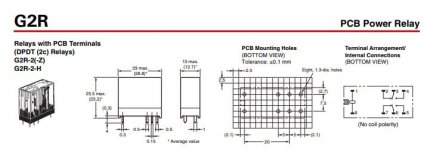
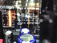
You're right, there is speaker protection on board. In this particular case, otiginally it is Omron G2R-2 12VDC.Quick question, I see there is relays on the board, is this for the speaker protection? or must I order some speaker protection boards to.
Datasheet
Observe the proper pinning on the attached snapshot.
Note: there is also servo on-board so you don't have to worry about DC ofset.
Attachments
Last edited:
Good idea. This amplifier can not fit in these small commercial enclosures. I use large heat sinks (0.3 K/W) to achieve better sound at higher quiescent current.Will build my own enclosure for it.
- Home
- Amplifiers
- Solid State
- A60(+) Amplifier. Build this?