TNT, Santa could use your present as a sled! Attached ~113cm diameter freestanding monstrosity with conical CD exit included, k=0.5 worked this time 😱
🙂 Point it backwards and play some brass..
//
This is for the TAD TD-2001?
You could further smoothen the opening (lowering the flare rate) by lowering α(lpha) and perhaps increase L.
k = 5 seems a nice tradeoff value, but k = 10 would probably work even better. In any case, it's hard to avoid beaming with the TD-2001.
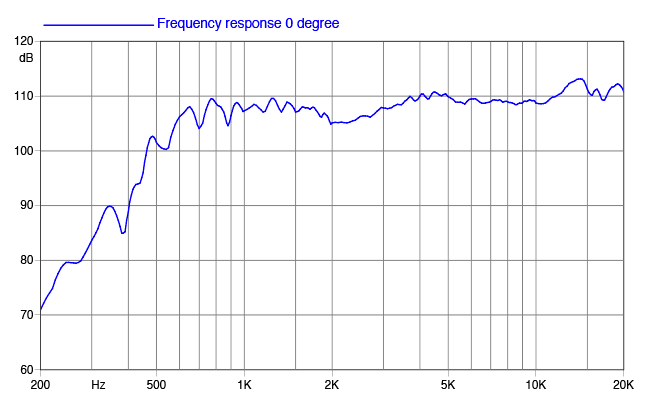
Faital pro hf10ak with 21 degree conical exit, that is what I have here so using it. I don't know exactly how long the conical exit is but estimating it by eye its about 1".
The HK10AK is a kind of 'poor man's TD-2001', but luckily with a much wider exit.
It does suffer from a similar dip > 1500 Hz, though.
Personally, I would sacrifice some DI for better throat impedance.
Some beaming (> 8000 Hz) isn't really annoying as long as DI is fairly constant in the midrange.
It does suffer from a similar dip > 1500 Hz, though.
Personally, I would sacrifice some DI for better throat impedance.
Some beaming (> 8000 Hz) isn't really annoying as long as DI is fairly constant in the midrange.
Last edited:
1. Driver only impedance
2. HF10AK + STH100 impedance
3. Half space, horizontal plane
4. Half space, vertical plane.
5. TD-2001 & HF10AK on RCF H3709 (speaking of loading).
2. HF10AK + STH100 impedance
3. Half space, horizontal plane
4. Half space, vertical plane.
5. TD-2001 & HF10AK on RCF H3709 (speaking of loading).
Attachments


Last edited:
And I ask the (rhetorical) question posed above.
Possibly and probably, I'd say.
That's an interesting question. I could slide the "throat" down the device towards the mouth and solve for an acoustic impedance the same way as for the regular throat but then this surface must have some shape. I guess it would have some sense to change it in the shape of the zeroth order mode. But then, how to determine that? From the pressure field isobars? What would it show us?Å - thats a good question I suppose. Take the throat definition and apply it to the other end?//
If you succeed with an equal, and, good model of both ends, it will show you how close the WG is to an ideal transformer. That must be interesting - no?
/
/
I simple model of a horn would be a tube. It has 2 ends. Right now you show impedance of only one end. It sounded in #5170 that you where on a interesting track. But I admit I'm on the border of my understanding here so... I might very well be out on deep water here claiming a horn being a transformer... with a primary impedance, a gain and a secondary impedance. But I think it should be OK....
//
//
Isn't the "output" impedance that of a freely propagating spherical wave (in a limit)? Do we need a waveguide to calculate that?
I would think that the horn exit would represent an impedance different from one just out in "thin air". Again - really guessing here... it has I suppose an output impedance - no? After some boundary layer, "thin air" is encountered.
//
//
Found this:
"The impedance at one end of a pipe of length L is determined by the pipe’s shape and length, but also by its impedance at the opposite end, ZL." in section: Simulation.
https://www.institut3b.physik.rwth-aachen.de/global/show_document.asp?id=aaaaaaaaaaoqkul
And an other from a different place...:
"In the end, transformers, levers, and horns aren’t all that different."

//
"The impedance at one end of a pipe of length L is determined by the pipe’s shape and length, but also by its impedance at the opposite end, ZL." in section: Simulation.
https://www.institut3b.physik.rwth-aachen.de/global/show_document.asp?id=aaaaaaaaaaoqkul
And an other from a different place...:
"In the end, transformers, levers, and horns aren’t all that different."
//
There will be an impedance at any point along the waveguide. But, I agree, this isn't of much interest, to me at least. It would show the "impedance" transformation for whatever that is worth. The impedance at the mouth will not be a simple propagating spherical wave since it is in a boundary and that will change it. But I doubt that you will get anything meaningful.
You already show what is meaningful and what is the in-the-end what we are looking to do and that is control the sound radiation far field. Everything else is of far less interest.
You can define the mouth anywhere and any shape that you want since there is no real well defined mouth. You'll get numbers, but what to do with them is another question.
It was about me, of course. I overlooked those two sentences:
"You may have noticed that we omitted all the Source.* items. That's because we are satisfied with the default values at the moment. This means that an ideal (pulsating) spherical wavefront matching the throat opening angle will be used, which is just fine - we have nothing better at the moment anyway"
"In the above picture a spherical wavefront source, matched to the throat opening angle (7ş) is shown. If the opening angle was zero this would become a flat wavefront"
From them I understand that for Throat.Angle=0 the wavefront will be flat and for any other values will become spherical.
As all my tries were, let say generic, without any specific CD on mind, I've used 0 for throat angle so flat wavefront was applied automatically and consequently when I define Source.Shape as flat nothing changes.
After I put some angle(15) for throat angle and define flat wavefront, the difference (small and on high frequency) become obvious.
After I tried opposite, define spherical source:
"Source.Shape = 1 ;spherical
Source.Radius = 44
Source.Curv = 1
Source.Velocity = 1"
for 0 throat angle but there is no any change in graphs.
Probably again some wrong implementation or?
All have been done with OSSE profile.
I am going to try same with circarc
Last edited:
- Home
- Loudspeakers
- Multi-Way
- Acoustic Horn Design – The Easy Way (Ath4)