Phase plugs yes but never got far enough to simulate a whole waveguide. As this won't capture all the details of the mechanics of the internals (diaphragm modes, etc.), alone it won't work very well, IMHO.Mabat,
Have you tried simulating the CD phase plug in AKABAK?
If I were to simulate a phase plug, I would try to construct one for a spherical wave, matching a conical waveguide (as discussed here many many pages back).
....
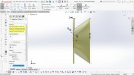
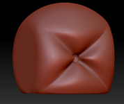
Simplified drawing of the Axi2050i on a horn....
You should be careful when evaluating results of your simulations of simplified axi2050 model because, as far as I remember, in axi2050 the membrane shape, the compression chamber shape, and phase plug channels shape were optimized using multiphysics approach, i.e. accounting coupling effects of mechanical modes of the membrane and acoustical cavity modes of the compression chamber.
What I was mostly interested for is how the directivity above 10khz is affected by a potential phase plug.
Many, like myself, would not be very concerned with "directivity above 10 kHz - more of an academic exercise than important.
Answer; probably a lot less than diaphragm resonances.
Many, like myself, would not be very concerned with "directivity above 10 kHz - more of an academic exercise than important.
Answer; probably a lot less than diaphragm resonances.
You have a point.
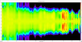
The above polar response (courtesy of member cask05) was made without the in-throat acoustic lens that Roy Delgado designed for the Axi2050 in order to spread out the polars above 6-8 kHz.
But I agree with Dr. Geddes that for a straightforward 2 way system - waveguide + woofer, a 1" driver is sufficient.
However, not every 1" driver is suitable for a crossover point below 1000 Hz and a little extra horn loading does help in my experience.
But I agree with Dr. Geddes that for a straightforward 2 way system - waveguide + woofer, a 1" driver is sufficient.
However, not every 1" driver is suitable for a crossover point below 1000 Hz and a little extra horn loading does help in my experience.
Attachments
Last edited:

And what are the merits beyond 10 kHz, other than "pretty pictures"?
Ever been to a movie theater where beaming horns were used?
The polar, while good, definitely isn't the prettiest polar I've seen. There's some waist-banding and the top octave could be better.
It's an example to illustrate that it's possible to get decent DI with a 2" driver, without resorting to a diffraction slot.
Last edited:
You should be careful when evaluating results of your simulations of simplified axi2050 model because, as far as I remember, in axi2050 the membrane shape, the compression chamber shape, and phase plug channels shape were optimized using multiphysics approach, i.e. accounting coupling effects of mechanical modes of the membrane and acoustical cavity modes of the compression chamber.
That's correct Dmitrij.
I don't think it's possible to simulate the Axi2050 without specific details of the innards, or a correct lumped-element model.
Development of the diaphragm alone was an engineering tour de force.
In this context Cask05 made a valuable discovery during his direct comparison of the Axi2050 with the TAD TD-4002 (for owners of the Axi):
"I realized that the Axi2050 has a clamped diaphragm on both the inner and outer diameters, and that, as the frequency rises, the effective moving mass of the diaphragm probably continues to shrink toward the position where the voice coil is attached (about midway between the ID and OD). If this notion was true, then it means that the diaphragm would still respond to increasing frequency, but with less and less moving area. So I tried the boost above the natural roll-off frequency (about 14.9 kHz), and found that it responded just as I had thought it might (unlike mass corner effects of other drivers). Of course, there are phase issues that arise in this regime, but I've learned that "better is better" when it comes to this sort of thing. The boost appears to work without added chatter, unlike dome-type 2" compression drivers.
So, bottom line, if using the Axi2050, I strongly recommend the 18 kHz boosting PEQ, even though it might look a little extreme, it seems to just compensate for the decrease in on-axis SPL. "
An interesting solution to deal with "modes" was used for the Axi2050.
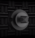
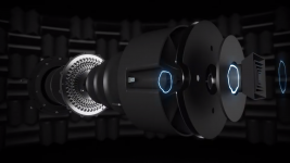
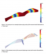
The motion of the diaphragm is adjusted to avoid exciting its resonances, applying a novel approach that Oclee-Brown referred to as “coupling maps,” which were used to evaluate the extent of resonant coupling in the frequency range of interest. The equations revealed that if the diaphragm resonances were exactly the right type of profile, the negative and positive components of the excitation could be made equal, so they don’t excite the cavity modes. The attached figures show the second mode for air and structure respectively. The pressure resulting from movement is combined across its surface and for every combination of structural and acoustic mode to produce the coupling map. In effect, diaphragm resonances may occur within the operating band and not radiate.
The motion of the diaphragm is adjusted to avoid exciting its resonances, applying a novel approach that Oclee-Brown referred to as “coupling maps,” which were used to evaluate the extent of resonant coupling in the frequency range of interest. The equations revealed that if the diaphragm resonances were exactly the right type of profile, the negative and positive components of the excitation could be made equal, so they don’t excite the cavity modes. The attached figures show the second mode for air and structure respectively. The pressure resulting from movement is combined across its surface and for every combination of structural and acoustic mode to produce the coupling map. In effect, diaphragm resonances may occur within the operating band and not radiate.
Attachments
In this context Cask05 made a valuable discovery during his direct comparison of the Axi2050 with the TAD TD-4002 (for owners of the Axi):
"
has he even actually done any analysis to show that the rolloff isn't due to mass....
I'm not convinced that it matters anyway. why does boosting a mass rolloff produce a worse result than say, a bandpass rolloff? sounds more like this is baseless speculation and wishful thinking.
its quite possible that these differences could just be a result of any other part of the design. ex. phase plug design (the TAD is very old)
That's correct Dmitrij.
I don't think it's possible to simulate the Axi2050 without specific details of the innards, or a correct lumped-element model.
Development of the diaphragm alone was an engineering tour de force.
In this context Cask05 made a valuable discovery during his direct comparison of the Axi2050 with the TAD TD-4002 (for owners of the Axi):
"I realized that the Axi2050 has a clamped diaphragm on both the inner and outer diameters, and that, as the frequency rises, the effective moving mass of the diaphragm probably continues to shrink toward the position where the voice coil is attached (about midway between the ID and OD). If this notion was true, then it means that the diaphragm would still respond to increasing frequency, but with less and less moving area. So I tried the boost above the natural roll-off frequency (about 14.9 kHz), and found that it responded just as I had thought it might (unlike mass corner effects of other drivers). Of course, there are phase issues that arise in this regime, but I've learned that "better is better" when it comes to this sort of thing. The boost appears to work without added chatter, unlike dome-type 2" compression drivers.
So, bottom line, if using the Axi2050, I strongly recommend the 18 kHz boosting PEQ, even though it might look a little extreme, it seems to just compensate for the decrease in on-axis SPL. "
Hi Roland,
Keith Hollandand and Philip Newell gave a succinct description of the key points of axi2050 design.

has he even actually done any analysis to show that the rolloff isn't due to mass....
I'm not convinced that it matters anyway. why does boosting a mass rolloff produce a worse result than say, a bandpass rolloff? sounds more like this is baseless speculation and wishful thinking.
its quite possible that these differences could just be a result of any other part of the design. ex. phase plug design (the TAD is very old)
It is recommended to read the available papers and articles related to the development of the Axi2050 to gain a deeper understanding of the acoustic engineering involved.
Some of these were posted before.
In light of the design objectives and solutions used, Cask05's conclusion makes a lot of sense.
Besides, he does not express a clear preference for the Celestion versus the TAD versus the BMS 4592ND and other drivers. A TAD TD-4003 (which he doesn't own) will undoubtedly beat the Axi2050 in terms of clean output in the top octave, but the Axi2050 is the only driver capable of 200-20.000 Hz.
B. Kolbrek considered 150, or even 100 Hz a feasible lower limit for hi-fi use, in combination with a suitable horn, based on experiments with early prototypes.
Last edited:
Hi Roland,
Keith Hollandand and Philip Newell gave a succinct description of the key points of axi2050 design.
Indeed, as was posted here
")
- Home
- Loudspeakers
- Multi-Way
- Acoustic Horn Design – The Easy Way (Ath4)