This was actually an exercise as a part of finding a shape of the exit wavefront of a compression driver. As I understand it now, for 1" drivers, if we assume that no other modes play a major role here, I could simply try adding the mode 0,1 to the fundamental and see if I can get a good match of the simulation to what I actually measure on the same waveguide. Then I can take that wavefront shape (i.e. the resulting complex sum of 0,0 and 0,1) and use it in other simulations for that particular driver to better match the reality. Right?
Last edited:
This was actually an exercise as a part of finding a shape of the exit wavefront of a compression driver. As I understand it now, for 1" drivers, if we assume that no other modes play a major role here, I could simply try adding the mode 0,1 to the fundamental and see if I can get a good match of the simulation to what I actually measure on the same waveguide. Then I can take that wavefront shape (i.e. the resulting complex sum of 0,0 and 0,1) and use it in other simulations for that particular driver to better match the reality. Right?
What you suggest is what needs to be done, yes, but manually!? Perhaps, but I would use SVD to find the best fit of a combination of the two modes to the measured data. This should be done complex - in theory - but I have found that real works pretty good (except at HFs, so it could yet be a problem here.)
Short of that ... maybe for two modes it may be possible by hand. You really only need to vary the higher mode in level, both positive and negative and find the best match. May not be too hard.
Both if complex is required (phase is important,) then I don't think that you could do it by hand. Hit or miss?
Or, because the mode 0,1 has a PWT cut-off ~ 16.5 kHz (for 1"), it can be directly measured by the multi-mic technique on PWT. As we have just shown, no higher axisymmetric modes are of interest - that much we already know by now.
You have good measured data ( I assume) and models of what each mode does, I would think that the PWT would be redundant. I'd try with what you have in hand.
Driven by mode 0,1 (horizontal/vertical and diagonal polars).
My knowledge is quite limited to follow the discussion following this post...
This pictures attached shows that this design is not correct? I compared to the pictures shown in post #7029 and the ones from my design look quite different (I assume worst).
Marcel,
Thanks for the clarification.
Just one last finding from attempts to import the model to Fusion 360.
-. If I use the script "SurfaceImport", I get the error I mentioned a few post back.
but...
-. If I use the script "CurvesImport" a dotted model is properly imported to Fusion 360. Of course this is not a solid object, but maybe there is a way to start from this.
I will keep looking for a solution.
BTW, if anyone wanted to try one of these high-z beaming monsters (on your own risk!), here's a one bit smaller (412 x 235 mm, 1" throat)-
You can do it
, although better compromises between loading and DI were posted before.Increased beaming above 8-10 kHz is not immediately experienced as less spatial radiation, but perhaps I, along with a number of French people, belong to a small minority who think so.
It seems that the Slot.Length item brings some new problems overall. I will have to reconsider how to implement it.
(This is the waveguide mga2009 designed.)
Looks suspiciously similar to the JBL rect. guide that was discussed many pages ago.
Last edited:
Increased beaming above 8-10 kHz is not immediately experienced as less spatial radiation, but perhaps I, along with a number of French people, belong to a small minority who think so.
Of course this also depends on the progression of DI and the final coverage angle in the top octave (preferably > 40°).


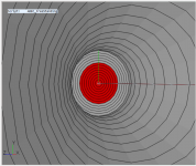
aragorus, nice would you mind posting the 0,1 mode source simulation?
Mabat posted the Source.Contours few days ago.
Paste this into the ATH model config file to get 2" 0,1 instead of spherical cap :
Should make the ABEC drawing look something like in the attachment
would you mind posting the 0,1 mode source simulation?Mabat posted the Source.Contours few days ago.
Paste this into the ATH model config file to get 2" 0,1 instead of spherical cap :
Code:
Source.Velocity = 2
Source.Contours = {
point p0 0.0 0.0
point p1 0.0 0.641026
point p2 0.0 1.923077
point p3 0.0 3.205128
point p4 0.0 4.487179
point p5 0.0 5.769231
point p6 0.0 7.051282
point p7 0.0 8.333333
point p8 0.0 9.615385
point p9 0.0 10.897436
point p10 0.0 12.179487
point p11 0.0 13.461538
point p12 0.0 14.743590
point p13 0.0 16.025641
point p14 0.0 17.307692
point p15 0.0 18.589744
point p16 0.0 19.871795
point p17 0.0 21.153846
point p18 0.0 22.435897
point p19 0.0 23.717949

line p0 p1 0.999397
line p1 p2 0.984974
line p2 p3 0.951726
line p3 p4 0.900611
line p4 p5 0.833100
line p5 p6 0.751126
line p6 p7 0.657026
line p7 p8 0.553465
line p8 p9 0.443352
line p9 p10 0.329747
line p10 p11 0.215764
line p11 p12 0.104477
line p12 p13 -0.001179
line p13 p14 -0.098496
line p14 p15 -0.185074
line p15 p16 -0.258894
line p16 p17 -0.318372
line p17 p18 -0.362407
line p18 p19 -0.390400
line p19 WG0 -0.402271
}
Should make the ABEC drawing look something like in the attachment
Attachments
Last edited:
- Home
- Loudspeakers
- Multi-Way
- Acoustic Horn Design – The Easy Way (Ath4)