Everyone, I am impressed by people insisting on not doing anything that might improve: noise, offset, or distortion and relying on feedback to do everything.
In truth, often we can get away with devices that come out of the same package. They are often made at the same time, and have the same color code.
However, let's say that you got some parts from your friend, some other parts from another project, and you don't know about color coding in regards to parts selection.
Then, you put a 170V, 170GR in parallel. What do you have then? For serious people to RECOMMEND sloppiness, JUST to contradict me, is impressive.
Matching jfets is one of the easiest things an amateur can do. All you need is a cheap voltmeter, a 10-100 ohm resistor and a 9V battery. It is best to get a plastic box with multiple compartments and label (with a marker) a current, for example 2 to 10. Then, with the 9V battery connected with the correct polarity short the GATE and one of the other leads of the jfet together and connect them to GROUND. Connect one side of the 9V battery to GROUND.
Take the extra lead and attach with a clip lead to the resistor. Attach the other side of the resistor to the 9V battery. Put the cheap voltmeter in V dc mode and measure across the resistor. Take a reading, put it in the right tray, and that is all there is to it.
Is this so difficult? It might 1/2 your open loop distortion and make your offset 1/10 of what it would be without matching, and would certainly prevent pathological mismatches that are still possible if you are sloppy.
scott wurcer said:
Get a good look that avatar will go soon. (AD524 paper, 1982)
Scott's personal picture.
I did a backup download .. of course .. if it goes away soon
")

john curl said:Everyone, I am impressed by people insisting on not doing anything that might improve: noise, offset, or distortion and relying on feedback to do everything.
1. This is about noise.
2. For offset we got servos.
3. For distortion cancelling, it was already mentioned that matching helps.
And who mentioned "pathological mismatching"?
If you got only one GR and one V, then you don't have anything to match anyway.
scott wurcer said:I would like to see more people try stuff rather than scaring them off.
No, Scott, no! I never smoked, sniffed, or took in mouth any stuff that teenagers sometimes use... Because I know that trying is the first step to abyss.
Once, to my embarrassment, someone showed me a photo of a JC-80 input stage composed of a 2SK240 pair and a 2SJ75 pair and ONE was a V, the other was a GR. It still worked, but WOW! How could a commercial manufacturer, push one of my designs so hard? Still, they were lucky. Many here will not be so lucky.
Matching primarily lowers even order distortion AND allows looser control from servos (a good thing), and SOMETIMES even helps noise paralleling.
You guys are way behind, I'm afraid. Please catch up. before I am a
Matching primarily lowers even order distortion AND allows looser control from servos (a good thing), and SOMETIMES even helps noise paralleling.
You guys are way behind, I'm afraid. Please catch up.
before I am a John Curl
I take your word for it.
Only time I have seen a real, on purpose, mismacth i an input pair
is in a preamplifier (old circuit) that used 1 BJT + 1 JFET
Maybe somone can know which one I mean.
The strive from my side is what John Curl stresses, time after time,
to make both inverted and non-inverted have as equal quality as ever is possible.
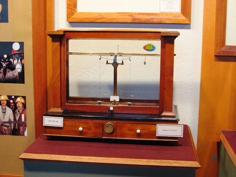
Like when we make one weighing balöance.
We match both sides closely to get a fair result.
Only what we put in will 'be visible'.
The weighing machines 2 arms should be as transparant as we can get it .. 99.999...%
Alöready the ancient Egypt were familiar with the balance a differential input pair:
I take your word for it.
Only time I have seen a real, on purpose, mismacth i an input pair
is in a preamplifier (old circuit) that used 1 BJT + 1 JFET
Maybe somone can know which one I mean.
The strive from my side is what John Curl stresses, time after time,
to make both inverted and non-inverted have as equal quality as ever is possible.
Like when we make one weighing balöance.
We match both sides closely to get a fair result.
Only what we put in will 'be visible'.
The weighing machines 2 arms should be as transparant as we can get it .. 99.999...%
Alöready the ancient Egypt were familiar with the balance a differential input pair:
Wavebourn said:This avatar would reflect wisdom & curiosity better:
So don't say that I don't have a sense of humor
BTW no Photoshop applied there.
I wish I could say the same. WavebournWavebourn said:I never smoked, sniffed, or took in mouth any stuff that teenagers sometimes use...
Nicotin-ist since 40 years back.
Wavebourn,
using the term linear in Physics and Mathematics is adequate. Linearity indicates that a conversion of a quantity to another quantity, like the output-versus-input signal amplitude, graphically appears as a straight line. Although the expressions are valid and relevant, they fail to quantify the wealth of detail in the sensitively perceived sound. The ambition to obtain good measured performance results in losses of valuable subjective (mostly non-expressible) qualities. In the context of sound perception linear does not mean good sounding. Good sounding amplifiers are nonlinear. Hearing is strongly nonlinear. The world is nonlinear.
Theoretical interpretations, factual explanations and practical experience make things predictable to a certain degree.
Lumba Ogir said:Good sounding amplifiers are nonlinear.
True. One good reason to hate "good sounding amplifiers".
Edmond&syn08,
It sounds like an agreement on this particular issue.That's why I detest good sounding amplifiers. One good reason to hate "good sounding amplifiers".
Noise measurements
Here's the noise measurement results.
I choosed a selection of bipolars, 10 each, some of them are well known low noise devices (LN), some are medium power devices with no noise spec in the datasheet (MP), and finally some are general purpose devices (GP). All devices are NPN only; the PNP pairs are still to be measured (I need to build another jig with reversed polarities) but usually PNP devices have lower noise.
I decided to build a small test jig, following the attached schematic. It's very simple, two low noise opamps gain stages, each with a gain of about 101 precise gain was measured using a 0.035% 1:10 MAX5491 resistive attenuator at the input and a HP3457 precision voltmeter. The Ic and Vce are set by the two 25K multiturn resistors.
After playing a little with the jig I somehow arbitrarily decided for a frequency of 5.8KHz. This is low enough to be in the amp bandwidth but high enough to avoid the flicker noise region (in particular for some MP devices). Opamps are LT1128 (AD797 was also successfully tried).
All measurements were done at Ic=1mA and Vce=6V. Noise density was measured by a HP89410 DSA. Before anything else, I measured the jig amp noise by shorting the collector and base terminals. This rendered an output noise of 53.4uV/rtHz, which maps to a 5.2nV/rtHz at the amp input. About 4.4 nV/rtHz are originating from the two 1k feedback resistors, which leaves a residual (opamp plus the rest) contribution of 2.8nV/rtHz.
For each device type, I measured and averaged beta. The resulting output noise Vn0 was also averaged over each 10 devices. Vni was calculated by using the measured opamp stages gains and the transistor stage gain gm*Rs, where gm=Ic/Vt and Rs=1k||9K (9k is the collector multiturn resistor setting Vce, all resistor values were measured accurately).
Rbb was calculated by solving the quadratic equation (assuming Kf=0). Here are the results:
Model Scope Beta Vn0 [uV/rtHz] Vni [nV/rtHz] rbb [ohm]
2N5551 GP 131 470.4 1.41 104.5
2N5210 LN 350 668 2.01 227.9
2SC2909 GP 155 490.8 1.47 115.4
2SC2362 LN 188 518 1.55 130.5
2SC2240 LN 174 322.4 0.96 41.5
MJE15030 MP 88 216.13 0.63 10.1
KSC3503 MP 107 245.7 0.72 17.6
2SC3601 MP 135 178.1 0.51 1.9
2SC2547 LN 274 176.8 0.51 1.7
Comments:
- Some of well known low noise devices are not that great at all; a bitter dissapointment was 2SC2362.
- I can barely understand why 2N5210 is defined as a low noise device. It was in fact the worse of all, worse than the popular 2N5551.
- As expected, the medium power devices are a strong contender; MJE15030 (8A/150V) has a rbb of only 10ohm, but a rather low beta and also the highest 1/f noise corner frequency of about 1KHz.
- Although the average rbb for the cheap MP KSC3503 from Fairchild is much higher than I originally determined, they are still very good in terms of noise. For pennies, you can't do better.
- 2SC3601 qualifies probably as the best discrete bipolar I have ever seen; with Ft=400MHz, Icmax=150mA and now with a equivalent input voltage noise of only 0.51nV/rtHz, this Sanyo device is truly amazing. They are not cheap, though...
- Finally, 2SC2547, the Hitachi device, is the winner. Only 1.7ohm rbb and a beta of 274! (high beta and low rbb are conflicting parameters).
- Iteresting enough, for 2SC3601 and 2SC2547 it is NOT rbb that dominates the noise, but the 1/gm term; increasing the collector current will allow lowering the noise even further (this is what I am planning to measure next).
- I checked the Vni values vs. my old Quantech and got very good concordance.
Here's the noise measurement results.
I choosed a selection of bipolars, 10 each, some of them are well known low noise devices (LN), some are medium power devices with no noise spec in the datasheet (MP), and finally some are general purpose devices (GP). All devices are NPN only; the PNP pairs are still to be measured (I need to build another jig with reversed polarities) but usually PNP devices have lower noise.
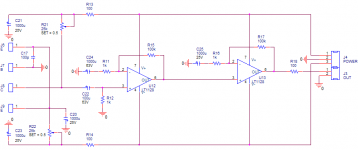
I decided to build a small test jig, following the attached schematic. It's very simple, two low noise opamps gain stages, each with a gain of about 101 precise gain was measured using a 0.035% 1:10 MAX5491 resistive attenuator at the input and a HP3457 precision voltmeter. The Ic and Vce are set by the two 25K multiturn resistors.
After playing a little with the jig I somehow arbitrarily decided for a frequency of 5.8KHz. This is low enough to be in the amp bandwidth but high enough to avoid the flicker noise region (in particular for some MP devices). Opamps are LT1128 (AD797 was also successfully tried).
All measurements were done at Ic=1mA and Vce=6V. Noise density was measured by a HP89410 DSA. Before anything else, I measured the jig amp noise by shorting the collector and base terminals. This rendered an output noise of 53.4uV/rtHz, which maps to a 5.2nV/rtHz at the amp input. About 4.4 nV/rtHz are originating from the two 1k feedback resistors, which leaves a residual (opamp plus the rest) contribution of 2.8nV/rtHz.
For each device type, I measured and averaged beta. The resulting output noise Vn0 was also averaged over each 10 devices. Vni was calculated by using the measured opamp stages gains and the transistor stage gain gm*Rs, where gm=Ic/Vt and Rs=1k||9K (9k is the collector multiturn resistor setting Vce, all resistor values were measured accurately).
Rbb was calculated by solving the quadratic equation (assuming Kf=0). Here are the results:
Model Scope Beta Vn0 [uV/rtHz] Vni [nV/rtHz] rbb [ohm]
2N5551 GP 131 470.4 1.41 104.5
2N5210 LN 350 668 2.01 227.9
2SC2909 GP 155 490.8 1.47 115.4
2SC2362 LN 188 518 1.55 130.5
2SC2240 LN 174 322.4 0.96 41.5
MJE15030 MP 88 216.13 0.63 10.1
KSC3503 MP 107 245.7 0.72 17.6
2SC3601 MP 135 178.1 0.51 1.9
2SC2547 LN 274 176.8 0.51 1.7
Comments:
- Some of well known low noise devices are not that great at all; a bitter dissapointment was 2SC2362.
- I can barely understand why 2N5210 is defined as a low noise device. It was in fact the worse of all, worse than the popular 2N5551.
- As expected, the medium power devices are a strong contender; MJE15030 (8A/150V) has a rbb of only 10ohm, but a rather low beta and also the highest 1/f noise corner frequency of about 1KHz.
- Although the average rbb for the cheap MP KSC3503 from Fairchild is much higher than I originally determined, they are still very good in terms of noise. For pennies, you can't do better.
- 2SC3601 qualifies probably as the best discrete bipolar I have ever seen; with Ft=400MHz, Icmax=150mA and now with a equivalent input voltage noise of only 0.51nV/rtHz, this Sanyo device is truly amazing. They are not cheap, though...
- Finally, 2SC2547, the Hitachi device, is the winner. Only 1.7ohm rbb and a beta of 274! (high beta and low rbb are conflicting parameters).
- Iteresting enough, for 2SC3601 and 2SC2547 it is NOT rbb that dominates the noise, but the 1/gm term; increasing the collector current will allow lowering the noise even further (this is what I am planning to measure next).
- I checked the Vni values vs. my old Quantech and got very good concordance.
Attachments
The 2N5210 example does not surprise me much. The part, developed more than 40 years ago, always had fairly high Rbb' of 200 or more ohms. The PNP equivalent would be slightly better, as are virtually all PNP parts. However this device was designed for 20ua -100ua operation for lowest noise figure. This is typically what we used, in those days, for tape recorder reproduce or phono input devices.
- Status
- This old topic is closed. If you want to reopen this topic, contact a moderator using the "Report Post" button.
- Home
- Amplifiers
- Solid State
- Addressing John Curl's concerns on low noise designs