The wires being connected to wrong channel on a working amp will only reverse what you hear as L and R but it also makes bias adjustment via the method in the manual meaningless because the method relies on using the speaker terminal as one of the measurement points.It would be nice of the power amp's left channel drove the left speaker and right channel drove the right speaker but I'm thinking this has no bearing on the issue(s) at hand, But I could be totally wrong about that.
There just seems to be so many man made errors with this
") that it makes it difficult to follow. Measuring voltage across any of the 0.47 ohms is the sure fire way to get the correct result.
that it makes it difficult to follow. Measuring voltage across any of the 0.47 ohms is the sure fire way to get the correct result.so ignore this, what you have on those 2 i think are corrct.when princomes off it normaly shows a pattern of what was solder print, but i dont think it is in this instance as this is where those 2 transistors are located, and the print that has come off is both soler points and non solder areas.the diagrams are not particularly clear.if i am correct and although it isnt very clear, im sure this is that seciton of the print
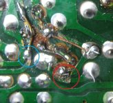
If you look at the attached, circled in red, to me looks like the solder pad is almost folded over and isnt connected to the component
The blue one could be connected to the other track, so i would take that off and re do the connection
That circled in red solder pad had lifted but looked still intact and was soldered to the component. But to be certain I soldered in a bridge. I re-flowed the circled in blue connection and it is not in contact with that other track - no continuity.
The wires being connected to wrong channel on a working amp will only reverse what you hear as L and R but it also makes bias adjustment via the method in the manual meaningless because the method relies on using the speaker terminal as one of the measurement points.
There just seems to be so many man made errors with this
Ain't that the truth.
To quote Monty Python...."My brain hurts."
Measuring again across all of the 0.47 ohm resistors, each on the left side group read a few millivolts. A little different than in post #196 but maybe that is because of varying lengths of time that the amp has been idling?
The right side group read 0.0mV across each one. And also as in post #196, bias is still 4.5 volts on both channels.
To avoid confusion, mostly mine, should I reverse that red and white wire on the speaker switch to what they were when I got the amp? The balance control will operate backwards but the power amp channels will be hooked to the correct speaker terminals.
That sounds good. Yes, bias current does drift with temperature. All normal.Measuring again across all of the 0.47 ohm resistors, each on the left side group read a few millivolts. A little different than in post #196 but maybe that is because of varying lengths of time that the amp has been idling?
Bias is the voltage across the 0.47 ohm resistorsThe right side group read 0.0mV across each one. And also as in post #196, bias is still 4.5 volts on both channels.
Offset (which we are not measuring at this point) is the voltage at the speaker output as measured from ground. This should always be close to zero. If the voltage on the 0.47 ohm is 4.5 volts as measured from ground then you have DC offset problem which is unrelated to bias current.It sounds to me like you are measuring a DC offset on the faulty channel and that is what would happen if the speaker connections were reversed.To avoid confusion, mostly mine, should I reverse that red and white wire on the speaker switch to what they were when I got the amp? The balance control will operate backwards but the power amp channels will be hooked to the correct speaker terminals.
Given there is so much confusion over all this its best if you look at each speaker terminal feed and make sure it goes to the correct place. The output of each amplifier (the 0.47 ohm resistors) should ultimately go to the PLUS speaker terminal for that channel. The speaker negative terminal should go to ground.