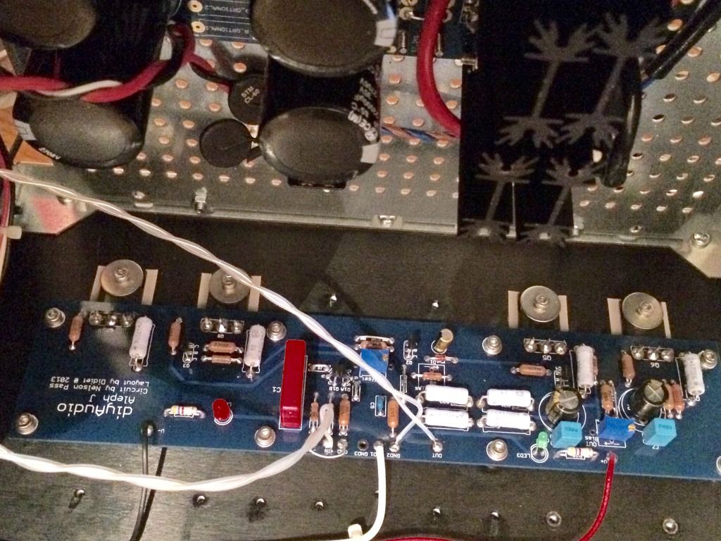
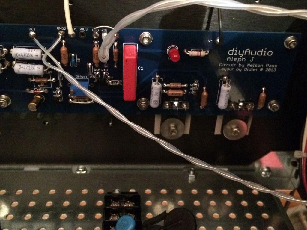
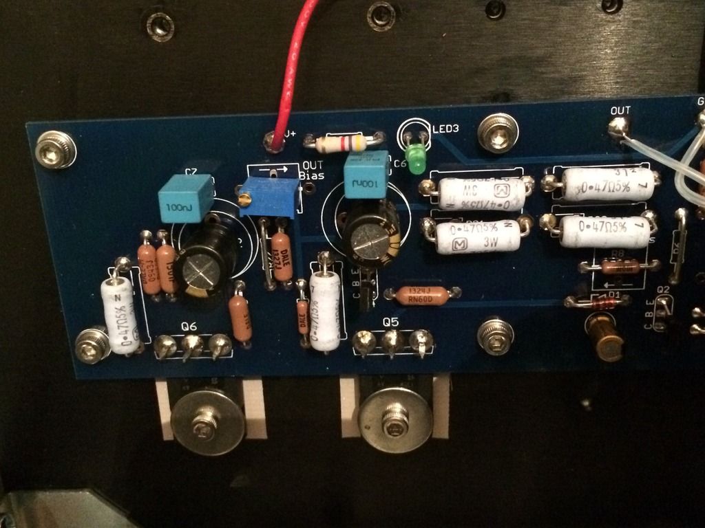
After almost 3yrs (delay due to two kids) my Aleph J is finally completed. Many many thanks to Nelson Pass, 6L6 and all others for their help. Lovely amp
Congratulation, you'll love AlephJ. I took 2years to complete it, postponed by twin boys birth. You got same chassis as mine. How much did you pay? I got mine for IDR3m ~ £160. How high do you set the bias? I want to try 1A/device with AC blowing directly to chassis.
From memory I paid about the same for the chassis including delivery. I'm running at 0.85A bias (400mV) and heatsinks sit at 47 degrees C. The only tweak I've done is use Hammond 159ZJ chokes in the PSU. I originally had trimpots for the LTP bias but swapped these for 1K resistors (I tried to adjust LTP bias using the trimpots but they didn't seem to make any difference). Great amp - hope you're enjoying yours as much as me.
Well I finally got around to building my Aleph J. Had the boards for over a year but just didn't get around to it till now.
I must say I am very impressed, not only does it sound great you can heat a small house with it
It is one of my favorite amps I have built. Very detailed and musical especially after letting it warm up for a bit. Was listening to a pair of shunt regulated 45 amps before the Aleph J and I am hard pressed to say which I like better.
What an amazing hobby, no matter how long I have been building amps/ preamps or how many I have built I am still amazed that I can build something that sounds so good!
Hi all,
Amp is built, boards are powering up. On one side I have approx 24vdc across the speaker terminals.
Clearly something amiss.
Any ideas where to start looking?
Pictures
I took a look at the schematic and if I was you I would take a close look at C2 and C7. If there is a problem there, shorted cap, solder bridge etc the 24DC would go straight to the output. Any shorted active part ,transistor, would do the same thing of course. Some plain old resistance readings at all points and compared to the good channel would be a good place to start as well. Take a magnifying glass and look at all the traces of the board especially where they are close together. I sometimes use a 10X loupe on suspicious areas, old eyes.
Last edited:
No these are ok, what's the purpose of the zip tie? It does look like Q1b is reversed on the photo! I hoped that it was, would have been an easier fix.
C2 and C7 are not shorted. Board looks ok, I'll check resistances and work through the schematic.
I'll also post some pics of the underside of the board.
C2 and C7 are not shorted. Board looks ok, I'll check resistances and work through the schematic.
I'll also post some pics of the underside of the board.
To encourage them to be the same temperature. Zip ties, thermal glue, and special heat sinks, are ways I have seen to connect the matched JFets thermally together.
Popular practice. I feel that as they are tested separately during matching, that binding them thermally might cause un-matching.
I confess to being an electrical dummy though, as a disclaimer. I have had both a couple of bad solder joints, and a reversed transistor pair so far.
Double check your power supply and wiring to the amp boards.
Last edited:
I would look carefully where the jfets are located. The legs are close together as well as the traces. Do compare the good board resistance values and voltage values at the same points for comparison. You should see a different resistance or voltage readings between the good vs bad board. With such few components it should not be too hard to do. With more test equipment it would be easier to locate the problem area but this way should work as well.
Thanks for the explanation bones13. My PS is working well and delivering +/-24v to the boards, shockingly EXACTLY 24v, not experienced that level of precision with any other power supply I've built. Power hook ups look ok.
Wdecho, having pulled the board today to inspect it this is where I'll start, thanks again, I had bent the legs of q1a so that the jfets met face to face so I guess it's a prime suspect.
I'll report back.
Wdecho, having pulled the board today to inspect it this is where I'll start, thanks again, I had bent the legs of q1a so that the jfets met face to face so I guess it's a prime suspect.
I'll report back.
More developments here. I tested resistances around Q1a and Q1b v the other board and did find a cold joint. Upon powering up I still had 22v on the outputs.
I then went through the board reflowing every joint bar the mosfets.
Powered up, smoke from R17/18/19.
I'll get some more of these ordered before I proceed with the trouble shoot.
I then went through the board reflowing every joint bar the mosfets.
Powered up, smoke from R17/18/19.
I'll get some more of these ordered before I proceed with the trouble shoot.
In automotive diagnostic terms we call that the smoke test. Now you have place to look for trouble. I would look closely at the Q 6, 7, and 8. It is a good chance they are being ground to the chassis instead of being insulated as they should be by whatever kind of insulator you are using. You can check for grounds on the mosfet legs with your ohmmeter and the metal tabs of the mosfets. The metal tabs should not show being ground to the chassis.
- Home
- Amplifiers
- Pass Labs
- Aleph J illustrated build guide


