To get or go without Speaker protection.
Thanks very much. You have gently persuaded me that US$80 is reasonable for good-sounding insurance.
I went without an SSR for years....
Basically, it depends. Or, YMMV.")
Thanks very much. You have gently persuaded me that US$80 is reasonable for good-sounding insurance.
The best part about these units is they are so easy to install (less than 5 minutes) and they are totally out of the way once installed. You forget they are there - except that there is no more turn on pop, and of course, they become the insurance against blowing speakers - when called into action.
The best part about these units is they are so easy to install (less than 5 minutes) and they are totally out of the way once installed. You forget they are there - except that there is no more turn on pop, and of course, they become the insurance against blowing speakers - when called into action.
Ya, before I hook anything to my highly modded Tektons, or my PAP Horns, I'm going to put this in. It's great that we can make these amazing amps for a lot less, but not so much if it takes out a 7k pair of speakers.

Hi X,
Referriing to post #371.
Are you using or have you used a soldering stencil for any of your sm soldering? My impression is that stencils are used if you have sloppy soldering techniques or if the components are very tightly spaced.
Not even sure if you could use a stencil in the skillet process.
Regards
Hi X,
Referriing to post #371.
Are you using or have you used a soldering stencil for any of your sm soldering? My impression is that stencils are used if you have sloppy soldering techniques or if the components are very tightly spaced.
Not even sure if you could use a stencil in the skillet process.
Regards
I used to use stencil for my pocket amps, but found that for small volume production, applying with a syringe was much faster than the setup and cleanup required after using a flat plastic spatula to squeegee the paste through. Then having to hurry to apply the components before the paste dried or else it would not be tacky to hold components for hot air process.
The hassle was not worth it and it did not make joints much neater than hand applied with a hypo syringe.
A big advantage with the hand applicator is that you can build a board in sections. Like the PSU first and check to make sure it works before moving on. Cannot do that wih stencil - you have to make the whole at once.
Maty,
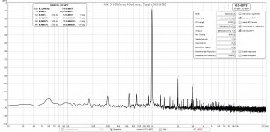
That plot is for 3.16Vrms into 10ohms or 1w rms. Not 39w.
That's why the F5 sounds bright and sharp. Some people like this sound though.
Alpha Nirvana 39 watts 8 Ohms, latest measurements, at 10 Ohms.
That plot is for 3.16Vrms into 10ohms or 1w rms. Not 39w.
Figure 8, spectrum distribution of the distortion at 1 watt, and you can see the dominant 3 rd harmonic, as well as 2 nd, 4 th and 5 th.
That's why the F5 sounds bright and sharp. Some people like this sound though.
Regarding surface mount soldering...I encourage friends to get training boards. I had to do warranted field repairs on PCBs over several decades and several jobs. Remember tin whiskers? This work followed the evolution from through-hole to mixed components to fully SMT. We replaced more surface mount boards rather than repair them in field. So I became very good at soldering with best practices, but rarely had opportunity to do surface work. I have avoided surface mount for years until recently. YouTube, and the like, provided lots or reference material to do some practice, so if you do not have any scrap PCBs laying around to practice on, then purchase some training boards. X and others have mentioned this before and it is great advice. They will be less than $10 with components included and the practice will up your game with no regrets. I find no preheat needed with 8-10 pins or less, but it is a correct practice. Kinda depends on if you warrant your work or if it is personal. Liquid flux and solder wick are helpful. Magnifiers and lots of photons help success. Lots of SMT components can worked with a 1/4 inch chisel tip iron with a little practice. Your equipment needs will be revealed as you practice, so I suggest get started with practice boards and the equipment you have. I definitely knew that I could do this just fine after seeing several videos... buffoons on display right next to experts!
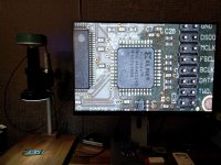
For SMD soldering to become very easy get a 60fps hdmi microscope.
The 60fps hdmi makes it real-time without lag.
Take a 180x zoom lens and a 0.5x barrow lens to double the working distance.
Tada, SMD soldering has become easy
The 60fps hdmi makes it real-time without lag.
Take a 180x zoom lens and a 0.5x barrow lens to double the working distance.
Tada, SMD soldering has become easy
Attachments
I've found hot plates are almost mandatory if the PCB has a heavy copper pour/large ground plane and you want/need to use a hot air gun for soldering. I did not use a hot plate when building the Lender pre-amp SMT daughter board, due to not actually owning one and not having any at my current job. What I like to use are two soldering irons, with small tips, and hold one in each hand to solder down resistors/diodes/two "legged" components. Using the two irons keeps the part from moving around and is also very hand for removing too!
Tweezers are also crucial for placement and moving the small parts around; my favorite are made by Aven, part number 18072EZ. They also have an assorted pack, 18480EZ.
My favorite soder-wick is Chemtronics 50-4-25. I recently purchased some non-refrigerated solder paste and the paste dried up inside the syringe...
Also keep high proof alcohol for cleaning up but don't drink any until the work is done.
Quick question regarding the SSR DC protection card. Why were MOSFETs chosen over mechanical relays? I had read somewhere, but never actually measured to verify, that audio can be effected when passing through the solid state switch.
Last edited:
Quick question regarding the SSR DC protection card. Why were MOSFETs chosen over mechanical relays? I had read somewhere, but never actually measured to verify, that audio can be effected when passing through the solid state switch.
It’s all in the SSR thread. Relays can arc and debris on contacts can degrade signal. Or can weld themselves shut in NC mode. Correctly chosen SSR’s have no measurable negative impact as I showed with measurements. They don’t arc, and they don’t wear out or degrade with use.
The topology is very close to those from this SE modules - go toInteresting topology. I think I will have to give this a solid look. I'm always on the lookout for class A MOSFET amps. This one has some 'trick' aspects to it!
Produkte - Andre Buscher Audiotechnik - Puristische Eintaktverstarker
Main difference is the use of MOSFET's in the LTP input stage of Buscher's modules
Moderation Note: side discssuion split off https://www.diyaudio.com/forums/solid-state/346289-discussion-audio-nirvana-operation.htmll
Yes!
HD
Yes!
HD
Still continuing to listen to the Alpha Nirvana. Using a good DAC makes a difference! Finding that the lower noise output of my Cayin N3 connected via USB 3.0 improves detail, resolution, and soundstage. This amp is very resolving and will let you hear differences in your DACs when running high res FLAC files and good speakers.
I have played with the compensation caps, and pulling the amp out to swap caps, takes less than 1 minute. I have done it dozens of times and am really liking how the modular approach of having MOSFETs outboard and connected with Molex minifit quick releases is a joy for the amp tinkerer! How long does it take for you to pull a normal amp with underhung MOSFETs dirctly soldered to the PCB? You avoid it at all costs, right? Not anymore - it's no problem.
In fact, you could leave the MOSFETs connected and we can make new amp topologies with the same plugs and you can even swap out amps in a jiffy. Just imagine, one chassis with one PSU and one set of outputs and all the ancillary binding posts, RCA's, EIC's, SSR's switches, trafos, etc. all common amp items.
Now, when we make a new amp - we just make a new core board with the nice Molex connectors Snap in the MOSFETs and PSU cables and speaker cables (also on quick connects). Presto - amp rolling!
Last edited:
For SMD soldering to become very easy get a 60fps hdmi microscope.
The 60fps hdmi makes it real-time without lag.
Take a 180x zoom lens and a 0.5x barrow lens to double the working distance.
Tada, SMD soldering has become easy
true, but this does the job very well for SMD soldering:
Magnifying Glass Lens LED Light Visor Head Loupe Jeweler Craft Hobby Magnifier A 602668553302 | eBay
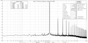
After switching to the Cayin N3 as a USB 3.0 DAC, fed by Jriver - I noticed that the noise floor of the Alpha Nirvana is now really much better. The 60Hz mains hum peak is almost non-existent, maybe 6dB above -125dB noise floor. So looks like the SLB really is doing its job once you have the right DAC in place. I decided to test the right channel under max excitation from the N3 DAC. I was able to get 19.3Vrms (according to O-scope) into 10ohms, for 35w into 10ohms. This level was too high for the audio input (even with a 1:10 divider) so could not get FFT until I backed it down a notch to 17.78Vrms. In any event, I was unable to achieve clipping. The measured THD at the highest setting I could put into the Focusrite was 0.093%.
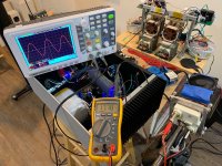
Test Setup with fan-cooled EBC 300w 10ohm non-inductive dummy load:

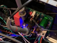
Closeup of Right ch amp under test with O-scope probe leads:

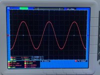
Here O-scope shot at 54.4Vpp, 19.3Vrms into 10ohms (35W):

Here is the FFT for 17.77Vrms into 10ohms (31.5W):

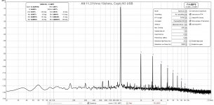
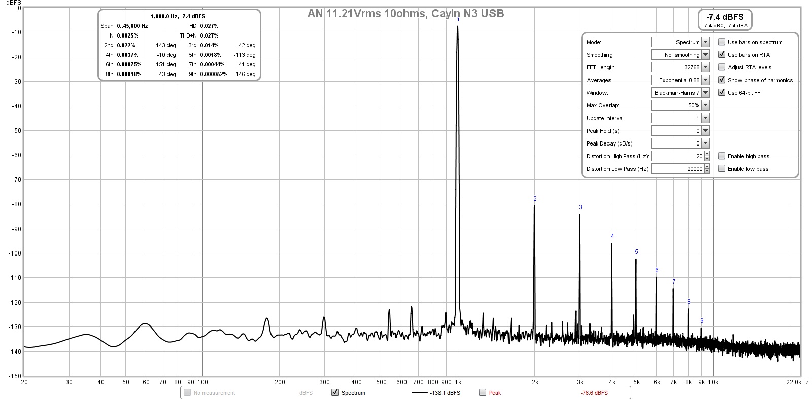
Here is what the FFT looks like for 11.21Vrms into 10ohms (12.5W):

Here is the FFT for 3.16Vrms (1W) into 10ohms:

The amp is now running with a BD140 for Q4 (V131) just to make sure it works so folks have a choice. This may have lead to a slightly higher THD level than left channel which used a KSA992.
Test Setup with fan-cooled EBC 300w 10ohm non-inductive dummy load:
Closeup of Right ch amp under test with O-scope probe leads:
Here O-scope shot at 54.4Vpp, 19.3Vrms into 10ohms (35W):
Here is the FFT for 17.77Vrms into 10ohms (31.5W):
Here is what the FFT looks like for 11.21Vrms into 10ohms (12.5W):
Here is the FFT for 3.16Vrms (1W) into 10ohms:
The amp is now running with a BD140 for Q4 (V131) just to make sure it works so folks have a choice. This may have lead to a slightly higher THD level than left channel which used a KSA992.
Attachments
-
 AN-SLB-v2-Full-Power-Test-04.jpg454.2 KB · Views: 824
 -
 AN-SLB-v2-Full-Power-Test-Closeup-07.jpg377.9 KB · Views: 795
 -
 AN-SLB-v2-Full-Power-Test-54.4Vpp-06.jpg214.2 KB · Views: 800
 -
 AN-17.77Vrms-10ohms-Cayin-N3-FFT2.jpg240.7 KB · Views: 801
 -
 AN-11.21Vrms-10ohms-N3-USB-DAC-FFT2.jpg237.6 KB · Views: 883
 -
 AN-3.16Vrms-10ohms-N3-USB-DAC-FFT2.jpg239.7 KB · Views: 1,281
Last edited:
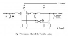
The topology is very close to those from this SE modules - go to
Produkte - Andre Buscher Audiotechnik - Puristische Eintaktverstarker
Main difference is the use of MOSFET's in the LTP input stage of Buscher's modules
Interesting but not the same from several aspects:
- Missing a BJT between the two legs of the LTP for the VAS,
- Missing a reactive CCS that allows the high efficiency of a push pull amp while still being a SE amp.
- Missing bootstraps to allow higher headroom
- Missing tricks to shape DF vs frequency
Attachments
In fact, you could leave the MOSFETs connected and we can make new amp topologies with the same plugs and you can even swap out amps in a jiffy. Just imagine, one chassis with one PSU and one set of outputs and all the ancillary binding posts, RCA's, EIC's, SSR's switches, trafos, etc. all common amp items.
Now, when we make a new amp - we just make a new core board with the nice Molex connectors Snap in the MOSFETs and PSU cables and speaker cables (also on quick connects). Presto - amp rolling!
I love this idea, it works well for me in the Yarra's case. I have swapped preamp modules like the Melbourne, USSPA, WBA19,etc....while keeping all others parts as constants.
X, please make the SLB as the default powersupply in all future power amp design, it is an important part of the amp system.
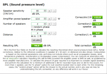
Obviously I have to think only of my second audio system, which is the one I can enjoy with my quality recordings. In the most demanding case but in the near field, 80 dBSPL continuous + DR15 = 95 dB (I usually hear about 65 dBSPL continuous). Modern commercial recording has DR < or << DR10. My last crap: Moulin Rouge - Music From Baz Luhrmann's Film (2001), CD, EU DR7
11.21Vrms into 10ohms (12.5W)
Pro-Audio and Lighting Calculators : dBs, time, Hz, DMX ...

11.21Vrms into 10ohms (12.5W)
Pro-Audio and Lighting Calculators : dBs, time, Hz, DMX ...
Attachments
Last edited:
- Home
- Amplifiers
- Solid State
- Alpha Nirvana 39w 8ohm Class A Amp