That would give 12.5 watt class A @ 4 ohm, probably max 32 watt A/B; class A efficiency of 12.5 %
Besides, a single pair of IRFP's would blow up more sooner than later.
Nelson Pass used double pairs of the same mosfets with the same quiescent for a reason in his Aleph J (which correctly specifies 25 watt class A @ 8-16 ohm using the same quiescent current....).
I'm interested in your method of calculation to come to 12.5w & 12.5%. How did you reach that conclusion?
My quick sim shows about +/17.0v rails, 1.86A bias current, and 62W dissipation per channel for 28.3Vpp or 25W into 4ohms or about 40% efficiency. More tweaking needs to be done by Hugh though to optimize harmonic profile.
31 watts for a mosfet power trannie, what is the actual heatsink temperature are you getting?
and how long does it take for the case/sink temperature to settle down to a fixed
temp?
and at what ambient temps do you test?
Hummm... 2 MOSFET by channel
About 120 watts by channel -> 240 watts in stereo in a small room (about 23 m3). I think it is too much in July + August (heat + hummid) in the Mediterranean coast, at least in Tarragona.
The answer, to my regret, is NO.
class A amps are hottest at idle when not delivering music to the speakers, at some point they actually cool down when volume level is high...
I'm interested in your method of calculation to come to 12.5w & 12.5%. How did you reach that conclusion?
20V rails; Iq 2,5A.
Ipk-pk = 5A.
5Apk-pk = 1,77A RMS.
Voltage swing class A with 4 ohm load = 1,77 x 4 = 7,07 VRMS.
Power output class A = 7,07² / 4 = 12,5 watt.
With 50 watt dissipation for each mosfet the power efficiency is 12,5 / 100 = 12,5 %.
at 50 watts per power trannie, i am really concerned with the long term reliability of this amp....
i was eyeing the ACA using the 48 volt rails, but the resulting device dissipation of 48 watts per device prevents me from using the irfp240, too much to ask for that device, a hockey puck mosfet perhaps...
i was eyeing the ACA using the 48 volt rails, but the resulting device dissipation of 48 watts per device prevents me from using the irfp240, too much to ask for that device, a hockey puck mosfet perhaps...
31 watts for a mosfet power trannie, what is the actual heatsink temperature are you getting?
and how long does it take for the case/sink temperature to settle down to a fixed
temp?
and at what ambient temps do you test?
The above 17v 4ohm sim was never tested. I can tell you that the amp I built is +/-28.5v rails, runs at 1.65A bias current and dissipates 47w each or 94w per channel. Heatsink temp has two small 57c hotspots immediately next to MOSFETs and 52C to 54C over rest of heatsink. About 45min to warm up to max temp. I measured 41w output before clip. Using alumina heatsink spacers (1mm) and CPU cooler thermal compound. Body temp of FQA 280w MOSFETs is about 72C. Ambient temp is 20C. Using DIYA store Dissipante 4U x 300mm chassis with UMS heatsinks. Trafo is Antek AN-6224.
PSU is SLB with LT4320 ideal rectifier bridge, 4x15,000uF caps in CRC with 0.2R 10W resistor and cap multiplier with circa 3v drop. Output ripple is circa 1mV rms.
Last edited:
you are lucky, you have 20 degrees ambient, in my part of the pond, that can be 30 to 34 degrees C in summer...
how about simply replacing the two resistors and a bootstrap cap with an LND150 mosfet CCS so that that stage becomes a pure CCS?
there are those that are skeptical of your claims because of those parts..
how about simply replacing the two resistors and a bootstrap cap with an LND150 mosfet CCS so that that stage becomes a pure CCS?
there are those that are skeptical of your claims because of those parts..
If you remove the bootstraps, you can’t swing the voltage as high before clipping. It’s part of the toolkit of topology used by Hugh to get this amp to do what it does. Why would having a bootstrap make it harder to believe? I would think it’s the other way around. It’s the reactive nature of the CCS as provided by Q4 that makes this work. The top N MOSFET is a voltage tracking device, the bottom MOSFET provides the reactive current as sensed by Q4 across the source resistor.
In hotter climates, use a 5U x 300mm or 400mm chassis. Vunce has a 5U x 400mm and he reports 42C for the same dissipation. That would be it’s good for 30C to 32C ambient.
Other option: use in an air conditioned room. It gets darn hot here in Wash DC in the summer. I think worse than where you live. 98F (37C) and 80% humidity. We could not do it without A/C continuously. So my basement is also 20C when it is 38C outside.
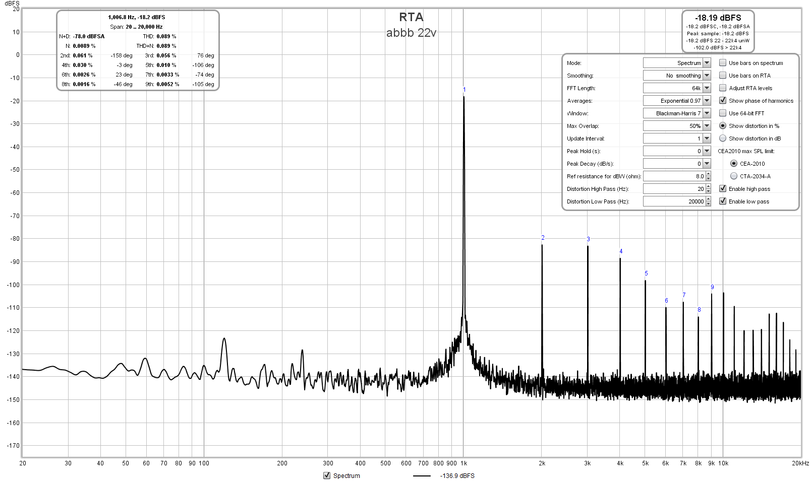
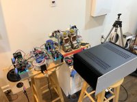
Great news, Gtose has completed his ABBB amp (and it is water cooled!). He is running some big +/-39.4v rails at 3A bias current and getting 60Wrms into 8ohms with only 0.089% THD before clipping. As ABBB is SE Class A with Aleph active CCS, these are 60W of pure Class A power.
20V rails; Iq 2,5A.
Ipk-pk = 5A.
5Apk-pk = 1,77A RMS.
Voltage swing class A with 4 ohm load = 1,77 x 4 = 7,07 VRMS.
Power output class A = 7,07² / 4 = 12,5 watt.
With 50 watt dissipation for each mosfet the power efficiency is 12,5 / 100 = 12,5 %.
Because of the active current source used, Ipk = 5A like a class A pushpull (Ipk-pk = 10A). Irms = 3.54A. Power = 3.54^2 * 4 = 50W. Voltage swing for 50W = 14.14Vrms = 20V peak which matches the power rails. So like a push pull for efficiency but because only one half is driven by the VAS the even order harmonics don't cancel so it's like an SE amp for distortion profile. But this has been said many times before....
Because of the active current source used, Ipk = 5A like a class A pushpull (Ipk-pk = 10A). Irms = 3.54A. Power = 3.54^2 * 4 = 50W. Voltage swing for 50W = 14.14Vrms = 20V peak which matches the power rails. So like a push pull for efficiency but because only one half is driven by the VAS the even order harmonics don't cancel so it's like an SE amp for distortion profile. But this has been said many times before....
Sorry you are wrong! You are exaggerating the current by a factor two.
Why does it seem so difficult to do the basic math, which applies to virtually all class A amps "except Nirvana"?? Hilarious....
Just take First Watt Aleph J for comparison, which is the same topology (apart from bootstrapping):
also 5A pk-pk, giving 25 watt class A @ 8 ohm.
Aleph J would also not give more than 12,5 watt class A @ 4 ohm; it is specified for the 25 watt class A at 8 ohm (and higher).
Aleph J also has the correct rail voltages for that power.
In the example above you'd have also 25 watt class A @ 8 ohm current wise, but the 20V rail voltages are too low for that.
X's calculation for a 4 ohm class A amp in post #362 is about good: 17V rails and 3,5A Iq would make a 25 watt @ 4 ohm class A amp.
But please attack me in my "own" thread from now on!
Last edited:
I had a pretty long listening session last night with the Alpha Nirvana and Alpha Omega and also the Glass Harmony (a 50w SE Class A with reactive microwave oven transformer choke load). All three amps sound great, but there are subtle differences. Will need more time to clarify the differences.
Attachments
What is this Alpha Omega you speak of? I am still curious to how the Nirvana compares to the smaller Alpha 20 (which I really enjoy).
Maty Tinman, have you built or listened to the Alpha 20? I am running it biased at 1.96A for 4 ohm loads and the heat isn't much of a problem, all though it is winter in New England...
Maty Tinman, have you built or listened to the Alpha 20? I am running it biased at 1.96A for 4 ohm loads and the heat isn't much of a problem, all though it is winter in New England...
Hi Shawnstium,
Thanks for your post. You will find the Nirvana easily eclipses the ALPHA 20.
At the completion of the R&D of the ALPHA, X and I continued with more work to see if we could make something even better with a view to a commercial product.
I came up with the Omega. It is more complex than the ALPHA, and more efficient. X built it very quickly and did some initial tests. It was indeed a better amp, confirming my thoughts that I was on the right track. In the development of amps, two out of three amps are discarded for one reason or other. Then, I had a few more ideas, and so the ALPHA Nirvana was born, so we decided to give it to the community. This helps me too; more experience, more tests, more listening sessions, it gives more possibility of something even better. Most design starts as a doodle in a coffee shop, so the attitude is important and a technical builder is very helpful to the flow of ideas. Since the Nirvana, I have created another design, and achieved more simulated results - an extremely useful method to minimise R&D costs - and I will sell this is as my Class A amplifier commercially out of Aspen. This will be my second Class A; my Glass Harmony was produced in 1994 but sold in very small numbers. It consumed 150W of heat per channel and produced 28W of glorious audio, but at 18% efficiency I never considered it was commercial. The Nirvana is 42.5% (40W with 94W used) and this is more like it.
The problem with this technology is that it requires a very long period of learning, gestation and prototyping to design a good amp. And innovation is rare; only Nelson Pass and a few luminaries have created truly original designs. I have been fascinated by amps and music all my life, built my first solid state amp in 1964, and in my forties I quite suddenly found that I could design things quite well. I started Aspen Amplifiers in 1995, and my first big sales came from the AKSA 55, which sold around the world. It was a conventional Lin/Bailey AB push pull SS amplifier but tweaked carefully to deliver good music. Since those days in the early 2000s I have designed all sorts of amps, many of them highly unconventional. In recent years I have had wonderful help from X, who builds all my amps very quickly and tests them thoroughly. I am 68 and do not much building now, my eyes are not wonderful, particularly with smd components.
I am watching Daanve with amusement. Getting ones head around a single ended push pull amp like the ALPHA is not easy, it defies categories, but I have hopes that eventually he will understand it. It is a Class A since both output devices never turn off; but it is not a Class AB at all, and when it clips, like most Class A amps it really clipped hugely.
I have moved along with the Omega, changed it completely now, and last night sent off the order for 100 pcbs to be manufactured. I will sell it as a 40W Class A amplifier, and I will be using forced air circulation, at least in the first amp. Eventually I will use it in monobloc and use passive cooling, but it will be four large heatsinks!
HD
If you remove the bootstraps, you can’t swing the voltage as high before clipping. It’s part of the toolkit of topology used by Hugh to get this amp to do what it does. Why would having a bootstrap make it harder to believe? I would think it’s the other way around. It’s the reactive nature of the CCS as provided by Q4 that makes this work. The top N MOSFET is a voltage tracking device, the bottom MOSFET provides the reactive current as sensed by Q4 across the source resistor.
bootstrapping is a circuit trick and purists for class A and single ended do look at it with raised eyebrows, personally i could not care either way...
you say you wanted more output swing before clipping, and ccs have compliance specs outside of which they cease to be, and add to that is the 4 volts gate to source threshold, an unavoidable loss...
in class A i believe the output devices must never saturate, so i think that removing the bootstrap capacitor and replacing one resistor with an LND150 depletion mosfets set to a bias of around 1ma or so improved the compliance of the output stage CCS, definitely better than just a resistor...
so you see, i criticize but i offer a solution, up to you to investigate and simulate to find out.....
since this is an open source design, i am asking a friend do a layout for this amplifier and with the gerbers produced will run around 20 boards and build the actual amp to test in real time the performance, efficiencies and the like...
Looking forward to seeing your design and test results from the build. Will you be making it with traditional fixed output (underhung) transistors or flying leads?
Looking forward to seeing your design and test results from the build. Will you be making it with traditional fixed output (underhung) transistors or flying leads?
i dislike flying leads for the output devices, lots of strays to contend with...
i am over that for a long time now, never looking back...
Thanks! It is always good to make someone's dayI am watching Daanve with amusement.
")
Also good to hear you repeat once more that it is single ended push pull. I got it from the beginning. However, X never got it and apparently still refuses to get it, "promoting" the design in post #2 from SEPP to SE rightaway (marketing gossip...); you know better and should have called him back.Getting ones head around a single ended push pull amp like the ALPHA is not easy, it defies categories, but I have hopes that eventually he will understand it.
Also in class A/B the output devices don't turn off completely, you know that.It is a Class A since both output devices never turn off; but it is not a Class AB at all, and when it clips, like most Class A amps it really clipped hugely.
In your design class A/B is perfectly possible, and, taking Iq into account, very likely.
Not all class A amps clip hugely (I guess you mean "hard"); it certainly is not a property of class A.
When your design clips "hard", the most likely cause is the "stiff" current source.
- Home
- Amplifiers
- Solid State
- Alpha Nirvana 39w 8ohm Class A Amp