D
Deleted member 148505
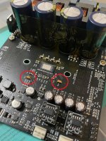
Feedback caps and resistors are now under the opamp socket, I did it so that they are now directly at the opamp pins. Once the socket is soldered, it is difficult to desolder, you can only change the opamp input resistors to increase the gain. (input resistor should be 10x the output impedance of your source, and no vol pot in between)
Do we have the ability to get the boards customized for balanced input + PFFB enabled + 2 V RMS input sensitivity? I could live with a little bit more noise.
I'm building a psu from a slightly different approach for class d. Probably overkill but I enjoy it.
Currently on my ver1 JLE3255 I am running LT4320 rectifier into 30kuf cap bank get from a 500VA 35v trafo. I get a nice 49V. I have measured the ripple using a true rms meter and it rises from pretty much zero at idle to peaks between 60 and 100ma at full load depending on music.
I am building a capacitance multiplier to try and will put that at the end of my cap bank before the DC input to the Sylph-D200. Can I use smaller local caps on the amp board for the big electrolytic. Nichicon FG do a 1000uf.
I would dial in the cap mx to try to achieve highest ripple reduction which means from 2v ro 4v drop out so I would be down between 45 and 47v.
Does thsy effect the PFFB at all?
Thanks
D
Deleted member 148505
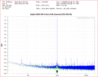
Performance-wise, using lower rail voltage will not affect the PFFB THD+N performance, you may get slightly better result with lower rail voltages.
Sound-wise, I can't guarantee if there are changes because it might be psychological..
For your Sylph-D200 module, I noticed sound improvement when I used a larger Silmic II (555-RFS25V100MF3#5) in the input coupling caps, 1uF 35V tantalum on C11 and C16 (T491A105M035AT). Larger AVDD cap (any 100uF 25V). You may get better sound if you change the same.
You can use smaller PVDD caps 1000uF each. Datasheet agrees.
Sylph-D200 is more tolerant on power supply quality differences, it can get good THD+N just by using a genuine meanwell supply.
I'm building a psu from a slightly different approach for class d. Probably overkill but I enjoy it.
Currently on my ver1 JLE3255 I am running LT4320 rectifier into 30kuf cap bank get from a 500VA 35v trafo. I get a nice 49V. I have measured the ripple using a true rms meter and it rises from pretty much zero at idle to peaks between 60 and 100ma at full load depending on music.
I am building a capacitance multiplier to try and will put that at the end of my cap bank before the DC input to the Sylph-D200. Can I use smaller local caps on the amp board for the big electrolytic. Nichicon FG do a 1000uf.
I would dial in the cap mx to try to achieve highest ripple reduction which means from 2v ro 4v drop out so I would be down between 45 and 47v.
Does thsy effect the PFFB at all?
Thanks
Last edited by a moderator:
D
Deleted member 148505
Thanks Lester. Should we try the opamp supply R short mod on Sylph-D200 or is that already implemented?
Got my VER2923 soldered in and opa1656 ready. Just the main caps to get.
R short mod is already implemented. What's the value of VER2923?
D
Deleted member 148505
D
Deleted member 148505
D
Deleted member 148505
Yes. I use a Salas DCG3 with gain set to a around x2 but I may up that a bit as my speakers are quite low efficiency
Were you able to complete your Sylph-D200?
Sylph-D200 V1 TPA3255 Final Mods (This is my personal amp config and I like it better than TPA3251)
Change C11, C16 with 1uF 35V tantalum capacitors (beware of the polarity)
Change AVDD cap to 100uF 16V to 25V
Change o/p filter to VER2923-682KL and 680nF (requires disabling PFFB)
OPA1656 buffer opamps
Attachments
D
Deleted member 148505
D
Deleted member 148505
On the 260Btl, what model of tank caps are the current recommended? Panasonic FC or other?
Yes Panasonic FC series is my recommended tank caps for the modules. If it is not available, you can use Nippon Chemi-con KZN, KYA, or KYB series.
Pitch = 7.5mm
Diameter = 18mm or 16mm
Much better if capacitor's height is around 35mm so that it will be similar with the heatsink's height.
Use 1000uF to 1800uF. Use 63V if rail voltage is 48V, use 50V if rail voltage is 36V to 45V(regulated)
Thanks,
Lester
D
Deleted member 148505
Lester you can hear difference between FC, KZN or KY ?
Hi Alex,
Actually no, maybe because their specs do not have drastic differences.
Regards,
Lester
Hi Lester. I just tried my Sylph D200 but it doesn't power up. One if the blue lights gave a very short burst but otherwise dead. No smoke or heat anywhere as far as I could tell. Didn't keep it powered too long.
Where to start fault finding and what precautions to take...load resistor on the speaker outputs?
Thanks
James
Where to start fault finding and what precautions to take...load resistor on the speaker outputs?
Thanks
James
D
Deleted member 148505
Hi James,
Do you have a different power supply like an SMPS to test it on?
In order for the blue lights to come on, the ramp up voltage should be quick.
If the ramp up voltage is slow, the inverting buck boost converter will not start properly.
It will start even without load.
Regards,
Lester
Do you have a different power supply like an SMPS to test it on?
In order for the blue lights to come on, the ramp up voltage should be quick.
If the ramp up voltage is slow, the inverting buck boost converter will not start properly.
It will start even without load.
Regards,
Lester
- Status
- Not open for further replies.
- Home
- Vendor's Bazaar
- Amplifier Modules and PCBs For Sale