If you have a suitable amplifier chassis, you can opt for SE-450-48. Just remove the fan and top casing cover.
Thanks Lester
D
Deleted member 148505
D
Deleted member 148505
D
Deleted member 148505
You're right about the ramp up speed. I guess I have some caps to charge which leads to a slow turn on.
Plugged in and turned on and it didn't start. So I unplugged the amp....let the caps charge and then connected. Sparks ensued and amp fires up! It is on 24/7 so this isn't an issue now its on.
I will provide a tiny daughtercard (15 x 10mm) that can be glued under the main PCB, to accomodate power supplies with slow rampup speed. Only contains 4 SMT parts and . For Sylph-D200 users, it's free, just need to pay small amount on shipping fee.
D
Deleted member 148505
Fantastic service to your customers as always Lester.
How does this small pcb adapt to Sylph-D200? Any smd needed by us?
Thankyou
Hi James,
SMTs are already soldered, there are 3 connections that should be soldered from daughtercard to main board.
There are already voltage taps under the PCB for V1.
For V1P: one trace should be scratched to tap the required connection, the 2 other connections are already exposed.
Just glue(thermal glue /heatsink plaster) the daughtercard under the PCB, then solder the 3 connections using link jumper wire.
Regards,
Lester
D
Deleted member 148505
Dual Supply Buffer for TICore260BTL is now ready for manufacturing")
Can you tell us more?
I have a TICore260BTL to get up and running and one of the points I need to address is to install the input opamps - I was about to order some OPA1656s but now wonder if this is the way to go?
D
Deleted member 148505
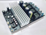
Yes, unfortunately someone has hoarded those heatsinks,Is there an alternative heatsink to the ATS-TI10P-519-C1-R3 that I can use with my TICore260BTL TPA3255 amplifier - it seems to be on back-order everywhere?
Thanks.
I will shift my PCB to ATS-TI10P-519-C1-R0 in the future if the stock is scarce. Size is the same but screw mount is different
If you can find 100mm x 30mm x 30mm, you can retrofit (drill and tap) and place copper shim underneath. (attached pic)
Can you tell us more?
I have a TICore260BTL to get up and running and one of the points I need to address is to install the input opamps - I was about to order some OPA1656s but now wonder if this is the way to go?
This buffer is made to remove the 4 extra input coupling caps in TICore260BTL. It will reduce the "haze" and "bloom" introduced by electro caps and will add clarity. Idea is from Brad Pitt
Attachments
Last edited by a moderator:
D
Deleted member 148505
I'd take the small add on for D200 and also maybe one of the buffer boards for 260btl. Could always send all to either me or Nauti to save international shipping.?
I have a spare heatsink I could lend to you Nautibuoy to get you going.
Sure, ETA is around 2 to 3 weeks.
I will contact you once the boards are ready to ship.Thanks Lester. It looks as though I should consider one of the buffer boards when they're available - will they be pre-populated? I guess the buffer board just plugs into the existing opamp sockets? Perhaps we can work out combined shipping to the UK with Jim.
Jim, thanks for the offer of the heatsink loan - how about you send me your spare one and I'll replace when they're in stock at Digikey (current date is Sept)?
Jim, thanks for the offer of the heatsink loan - how about you send me your spare one and I'll replace when they're in stock at Digikey (current date is Sept)?
D
Deleted member 148505
Thanks to Jimk04's kind offer of a heatsink and a Digikey delivery of the few parts I need, I now have everything I need to finish assembling my TICore260BTL module.
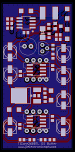
The first think I need to do is to apply the 'fix'. The instructions I have say to lift and rotate C17 and make a new connection to C16, as per the picture below. Instead of doing that I am thinking that I can cut the PCB tracks where I have put the red crosses, isolating C17 so there is no need to lift and rotate it - the connection to C16 would then be as per my yellow line. Can I just confirm that cutting the PCB tracks at the red crosses will actually isolate C17 or is there a via I can't see under the pad?

Edit: Actually, I've just remembered that the PCB is only two layer so I can see that there is no via under the C17 pad I need to isolate.
The first think I need to do is to apply the 'fix'. The instructions I have say to lift and rotate C17 and make a new connection to C16, as per the picture below. Instead of doing that I am thinking that I can cut the PCB tracks where I have put the red crosses, isolating C17 so there is no need to lift and rotate it - the connection to C16 would then be as per my yellow line. Can I just confirm that cutting the PCB tracks at the red crosses will actually isolate C17 or is there a via I can't see under the pad?
Edit: Actually, I've just remembered that the PCB is only two layer so I can see that there is no via under the C17 pad I need to isolate.
Last edited:
D
Deleted member 148505
Yes, this is an easier solution, thanks for the idea! You can also use jumper wire used in cellphone repairs.
Edit: Temp controlled soldering iron is a must, too much heat will melt and dislodge C17
You also need to remove and short out R8 and R10 for better sound.
Regards,
Lester
Edit: Temp controlled soldering iron is a must, too much heat will melt and dislodge C17
You also need to remove and short out R8 and R10 for better sound.
Regards,
Lester
Thanks to Jimk04's kind offer of a heatsink and a Digikey delivery of the few parts I need, I now have everything I need to finish assembling my TICore260BTL module.
The first think I need to do is to apply the 'fix'. The instructions I have say to lift and rotate C17 and make a new connection to C16, as per the picture below. Instead of doing that I am thinking that I can cut the PCB tracks where I have put the red crosses, isolating C17 so there is no need to lift and rotate it - the connection to C16 would then be as per my yellow line. Can I just confirm that cutting the PCB tracks at the red crosses will actually isolate C17 or is there a via I can't see under the pad?
Edit: Actually, I've just remembered that the PCB is only two layer so I can see that there is no via under the C17 pad I need to isolate.
Last edited by a moderator:
Thanks Lester.
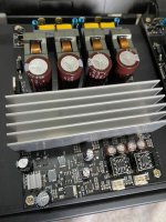
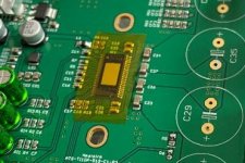
Another question if I may. the board i have acquired has a plastic foil over the amplifier chip, like this;

I assume this is covering a heat-transfer adhesive pad on the chip so I just need to peel off the foil and install the heatsink - no additional heat transfer paste required?
Another question if I may. the board i have acquired has a plastic foil over the amplifier chip, like this;
I assume this is covering a heat-transfer adhesive pad on the chip so I just need to peel off the foil and install the heatsink - no additional heat transfer paste required?
D
Deleted member 148505
I only put it there for ESD protection while it's being packed and shipped.
You need to remove it and put a very small amount of non-conductive CPU thermal paste (I'm using Arctic MX2).
Regards,
Lester
You need to remove it and put a very small amount of non-conductive CPU thermal paste (I'm using Arctic MX2).
Regards,
Lester
Thanks Lester.
Another question if I may. the board i have acquired has a plastic foil over the amplifier chip, like this;
I assume this is covering a heat-transfer adhesive pad on the chip so I just need to peel off the foil and install the heatsink - no additional heat transfer paste required?
Attachments
- Status
- Not open for further replies.
- Home
- Vendor's Bazaar
- Amplifier Modules and PCBs For Sale