I have done the fix

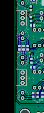
however, I'm slightly confused as to why it was necessary as all it seems to achieve is to connect the 'bottom' end of C17 to a different ground plane connection point at the 'left' end of C16? There is still continuity between the bottom of C17 and the bottom of C18 in spite of cutting the PCB tracks - am I missing something?
however, I'm slightly confused as to why it was necessary as all it seems to achieve is to connect the 'bottom' end of C17 to a different ground plane connection point at the 'left' end of C16? There is still continuity between the bottom of C17 and the bottom of C18 in spite of cutting the PCB tracks - am I missing something?
D
Deleted member 148505
The addition of R8 and R10 in V1A, V1B versions have made the ground plane reference of C17 different. Ground reference of C17 of TPA3255 is sensitive, it will not get the full power and the OCP will trip early.
TPA3251 does not have this problem so if we use the board with TPA3251, no fix will be needed.
Regards,
Lester
TPA3251 does not have this problem so if we use the board with TPA3251, no fix will be needed.
Regards,
Lester
I have done the fix
however, I'm slightly confused as to why it was necessary as all it seems to achieve is to connect the 'bottom' end of C17 to a different ground plane connection point at the 'left' end of C16? There is still continuity between the bottom of C17 and the bottom of C18 in spite of cutting the PCB tracks - am I missing something?
OK, thanks again Lester.
I'm almost ready to power up, heatsink installed, cap bank installed and I've just finished soldering up the op-amp plug-in boards.
I'll be using single-ended input so have set the jumper under the board to 'SE'.
Just one last question - with single-ended input I assume I connect my signal wires to In+ (hot) and Ground and ignore In-?
D
Deleted member 148505
Yes, just leave it floating. Also the pinout on TICore260BTL is different, refer to the picture below.
Careful on the polarity of the opamps (specially opamp to adapter mounting / soldering).
Careful on the polarity of the opamps (specially opamp to adapter mounting / soldering).
Attachments
Last edited by a moderator:

D
Deleted member 148505

Anyone using one of these with their amp?
http://connexelectronic.com/wp-content/uploads/2017/09/SMPS600RS.pdf
http://connexelectronic.com/wp-content/uploads/2017/09/SMPS600RS.pdf
D
Deleted member 148505
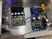
Hi Lester. I suggest you try installing some insulation material under the power supply module. In the picture below, which has two Mean Well SMPS units for tube filament duty, I used some spare glass/epoxy sheet, similar to PCB material, and ensured there's no continuity to the chassis via the stand-offs by using plastic types.

Anyway, I'm assuming you amp works so your power supply doesn't have problems with the amp's capatince at start-up?
Anyway, I'm assuming you amp works so your power supply doesn't have problems with the amp's capatince at start-up?
D
Deleted member 148505
There's no problem on startup since voltage ramp-up is quick.Anyway, I'm assuming you amp works so your power supply doesn't have problems with the amp's capatince at start-up?
There's a problem though when the ramp-down is not yet finished and the amp was restarted.
I placed a delay on the switcher so that the capacitors will be fully discharged on next power cycle. I also placed 1.8K ohms to bleed the capacitors faster. The daughtercard I designed will eliminate any ramp-up/down problems.
Hi Lester. I suggest you try installing some insulation material under the power supply module. In the picture below, which has two Mean Well SMPS units for tube filament duty, I used some spare glass/epoxy sheet, similar to PCB material, and ensured there's no continuity to the chassis via the stand-offs by using plastic types.
Maybe I'll just float the power supply by not connecting the earth terminal of SMPS300RS, then insulate the standoffs?
In Amir's review of modulus-286 he reported the same tingling sensation, it uses dual output version SMPS300RS too.
My only concern is that the mains leakage might show up on THD measurements.
Attachments
Last edited by a moderator:
D
Deleted member 148505
Thanks Lester.
I have ordered one of the SMPS600RS 48V 230V Power supply modules so it will be interesting to see how it works out.
I don't have the issue when the SMPS is running at 230V. I just noticed the tingling issue when I converted the SMPS to 110V. So I was puzzled by it.
I'm using SMPS300RS on my build and I'm feeling a tingling sensation when I slide my fingertips on the aluminum chassis.
Good wiring and good SMPS choice, this for the ASR review ?
D
Deleted member 148505
Good wiring and good SMPS choice, this for the ASR review ?
Hi Alex, yes I'm preparing for it
")

- Status
- Not open for further replies.
- Home
- Vendor's Bazaar
- Amplifier Modules and PCBs For Sale