You can disable PFFB now to increase the gain while waiting for your new buffer.
Wick out solder jumpers under the input coupling caps near the heatsink.
What's your attenuators impedance?
Thanks for your help Lester. I'll be placing an order for the buffer and it'll be be really useful to set the input sensitivity to around 1Vrms for full output but I'll leave PFFB alone as I can wait. Will I need to 'tweak' the buffer or is it something you will do?
I'm using an Academy Audio Muses volume control, which, IIRC, is equivalent to a 25K potentiometer, however, it is followed by a unity-gain buffer with very low output impedance so the TICore260BTL doesn't see the attenuator.
D
Deleted member 148505
No need to modify the daughtercard.
On your side, you need to remove the following parts from the main board.
CA3, RA4, CA6, RA8
CB3, RB4, CB6, RB6,
For SE, replace RA5, RB5 with 27K 0603 (I will provide those resistors). After you replaced them with 27K and want to go balanced, you need to bring back RA5, RB5 to 10K ohms.
While you're at it, you can put solder jumper on RA6, RA7, R8, R10 for sound improvements.
Also replace Nichicon Muse with Elna Silmic II 10uF
------------
Another possible upgrade is the output filter caps, 1uF 15mm, but those are the least priority.
D
Deleted member 148505
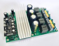
For TPA3251 lovers, TICore260BTL 36V supply with daughtercard can now be pre-ordered. Ship out date is on July 5.
TICore260BTL TPA3251 36V Stereo 100W 4Ω Amplifier Module RTR Free Shipping | jlelectronicsph
TICore260BTL TPA3251 36V Stereo 100W 4Ω Amplifier Module RTR Free Shipping | jlelectronicsph
Attachments
D
Deleted member 148505
We will start shipping out the items on July 1st.
Ship out date will be moved to July 5th. OPA1656 from Digikey was stucked in UPS Shenzhen facility for days.
Track your parcel delivery status. Powered by AfterShip.
D
Deleted member 148505
Hi jlester.
Do you still have ircore 2000 with smd pre installed? I bought and build your first generation with bd totem pole, time for some new stuff.
Thomas
Yes it's available in our website.
")
D
Deleted member 148505
@nautibuoy
Here’s your daughtercard with gain. Currently testing it with PFFB.
All electro caps in the daughtercard are for the dual power supply only.
Here’s your daughtercard with gain. Currently testing it with PFFB.
All electro caps in the daughtercard are for the dual power supply only.
Attachments
Last edited by a moderator:
Thanks for doing this Lester, greatly appreciated. 
I'm not doing anything with the amplifier until the daughterboard arrives.
I still need to do the main board modifications you listed in post #1282 - modifying PCBs always makes me nervous, especially ones with tiny smd parts!
I'm not doing anything with the amplifier until the daughterboard arrives.
I still need to do the main board modifications you listed in post #1282 - modifying PCBs always makes me nervous, especially ones with tiny smd parts!
D
Deleted member 148505
Oh no I think I forgot to include 27K 0603, is it there in the package?
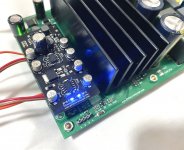
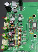
For modifications, short out the input coupling caps. Then put solder blob on encircled parts.
If you want to retain the unity gain, no other changes are needed. (you can try JimK04 daughtercard with unity gain for testing)
****
Since your daughtercard has gain=2.7, you need to remove all 0603 parts inside the yellow rectangle.
Then put 27K 0603 on RA5, RB5 (purple arrow on the attached pic)
Attachments
Thank you Lester.
I didn't find any 27k resitors but i can source a couple of them easily enough next time I order some parts.
The delivery contained two small packages;

I assume one for jimk04 and one for stretchneck?
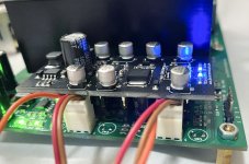
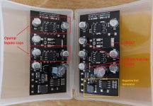
How do I know which is the high-gain daughterboard? I'm guessing the one on the right with the additional components around the opamp socket pins?

Cheers
I didn't find any 27k resitors but i can source a couple of them easily enough next time I order some parts.
The delivery contained two small packages;
I assume one for jimk04 and one for stretchneck?
How do I know which is the high-gain daughterboard? I'm guessing the one on the right with the additional components around the opamp socket pins?
Cheers
Last edited:
D
Deleted member 148505
Yes correct, high gain board is the one with resistors || capacitors on feedback pins.
You need to open all the packages and sort them out. Thanks!
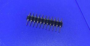
Also, I provided adapter round pins to attach the daughtercard to the mainboard. The long thin rounded pins should go to the mainboard side, the short thick rounded pins should be inserted on the daughtercard side.
BTW, since the release of Sylph-d200 we're now using opamp adapter pins that are thinner, we discarded the ones with thicker pins as they are making the socket holes larger.
You need to open all the packages and sort them out. Thanks!
Also, I provided adapter round pins to attach the daughtercard to the mainboard. The long thin rounded pins should go to the mainboard side, the short thick rounded pins should be inserted on the daughtercard side.
BTW, since the release of Sylph-d200 we're now using opamp adapter pins that are thinner, we discarded the ones with thicker pins as they are making the socket holes larger.
Attachments
Last edited by a moderator:
D
Deleted member 148505
The daughtercard is very simple. I just added a negative rail generator to provide -8.5V. Then I used LM317 to drop the voltage to +6V and LM337 to drop the voltage to -6V.
Then same pinout as the original, except that now the opamps are using +/-6V DC supply.
Then same pinout as the original, except that now the opamps are using +/-6V DC supply.
Attachments

D
Deleted member 148505
Hi guys. Just back from a few days away and the package from Ray is here. Thankyou. I have 2 slow ramp fix boards so I need to send one to stretcheck....if you let me have your address I'll sort that.
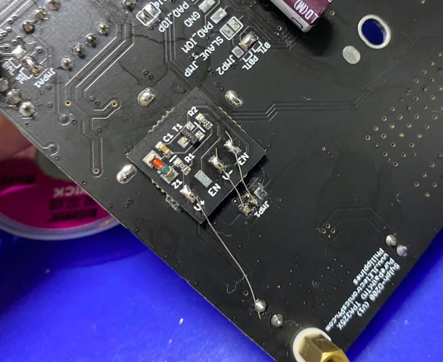
So to add this to D200v1 there are no trace cuts, just follow the photo...
Thanks
So to add this to D200v1 there are no trace cuts, just follow the photo...
Thanks

D
Deleted member 148505
Hi jimk04, and others with Sylph-D200 V1 board.
We have placed white goo in that place, only EN middle trace is currently exposed.
Please be extra careful in peeling off the white thermal glue as it may peel off the traces. You need to cut the white goo in a crisscross pattern with a blade before scratching it with a finger.
Also if you haven't acquired the output inductors, using 6.8uH VER2923-682KL / AGP2923-682KL will produce smoother highs when PFFB is disabled.
But when PFFB is enabled, both 10uH and 6.8uH will have the same sound, the quality of output cap will determine which one will be better.
Regards,
Lester
Attachments

- Status
- Not open for further replies.
- Home
- Vendor's Bazaar
- Amplifier Modules and PCBs For Sale