No problem Ray. I was just reading the last few pages again and saw Lester comment on 4 for Stretchneck and 1 for me!
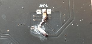
Thanks Lester. To confirm. I've removed the white glue covering the link wire connection. I remove that and the cap at JMP1 centre pad and then wire up the 3 connections to the module as per the previous photo.?
Thanks Lester. To confirm. I've removed the white glue covering the link wire connection. I remove that and the cap at JMP1 centre pad and then wire up the 3 connections to the module as per the previous photo.?
Attachments
D
Deleted member 148505
No problem Ray. I was just reading the last few pages again and saw Lester comment on 4 for Stretchneck and 1 for me!
Thanks Lester. To confirm. I've removed the white glue covering the link wire connection. I remove that and the cap at JMP1 centre pad and then wire up the 3 connections to the module as per the previous photo.?
Ohhh nice I thought the glue had covered the smt pads.. Yes remove all and wire up the 3 connections as per previous photo. We're also using heatsink thermal glue to stick the daughtercard under the board.
Attachments

D
Deleted member 148505
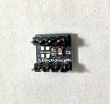
Nice soldering skills, you can also cover the baby board with kapton tape to secure it.Surgery done including the tantalum! One is a bit wonky which annoys me but I don't wish to burn it my resoldering too much!
I used double sided foam tape to attach the baby board
Please don't post pics showing clear underside of the IC, it will show some secrets. Your camera is very clear haha
D
Deleted member 148505
While you're at it, please remove the bypass cap under the soic adapter board.
Yes please")
Do you want me to remove that photo Lester...if I can?!
Yes please
Attachments
Last edited by a moderator:
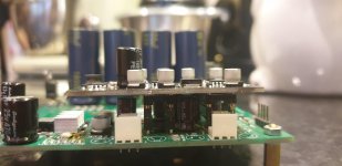
Busy day! My main amp has been the 260btl but I have the D200 in there as of today. So next job is doing the dual supply daughter board mod. Removed the input caps as they were Muse ES and I can reuse them. Will listen to the d200 for a good while first.
Lester is there any point in adding some film cap bypass for the opamp bypass electrolytic?
So I have 2 of Lester's fine amps and I will probably sell one on. I shall ask the buyer to pay Lester directly as he has been an absolute faultless vendor with unprecedented backup and I would like to pay him some dues back.
Attachments
Last edited:
D
Deleted member 148505
Hmm I haven't tried it yet. I think if you perform a modification, you need an identical module to compare it with. Otherwise you will be biased to your 'new' mod.Lester is there any point in adding some film cap bypass for the opamp bypass electrolytic?
Thank you for your kind gestureSo I have 2 of Lester's fine amps and I will probably sell one on. I shall ask the buyer to pay Lester directly as he has been an absolute faultless vendor with unprecedented backup and I would like to pay him some dues back.
. No need to pay back since this endeavor is currently self-sustaining. Good reputation and customer relationship are more important. Though if the donation is ultra huge we will gladly accept it lol JK.the quality of output cap will determine which one will be better.
Regards,
Lester
Hello
what are the best capacitors?
The important thing is the dv/dt?
Best regards
Roger
D
Deleted member 148505
Hello
what are the best capacitors?
The important thing is the dv/dt?
Best regards
Roger
Usually bigger poly caps have better parameters, or by using smaller parallel capacitors.
Paralleling output caps in our module is not advisable since there will be some stray inductance when using long leads.
You can check slaa701a for output capacitor selection, starts at page 30: https://www.ti.com/lit/an/slaa701a/slaa701a.pdf?
Regards,
Lester
Attachments
Capacitors
Thank you
Documents already registered.
I will add
Switching Amplifier (Class D) Basics | Audioholics page 2.
I thought you had found a must see.
Research at Mouser, for a mkp, gives 1 single capacitor an EPCOS / TDK B32672 and a KEMET PHE426 would be possible, but thicker 9.5mm and out of stock.
In Pet the Wima mks4.
Best regards
Roger
Will revive my GB150D pcb.
Hello Lester,
I am looking to populate the boards I purchased from you and I have a some beginner questions,
- For R14, what resistor did you use on the board in your pics? I am having trouble finding a match that will fit and allow an inductor to be wrapped around it like your pic.
- For D3 and D4, the example of "PDZ6.2BGWX" is an SMD with a zener current of 50na, would Vishay BZX55B6V2-TAP with 100na work?
BZX55B6V2-TAP
- LED1, a standard 2.2v 20ma LED is fine?
- C6 and C7, Mouser is out of UPW version, would UPJ be fine?
UPJ1J331MHD Nichicon
- CS1 and CS2, I know my eyesight isn't as good as it used to be but I cannot find them on the board although they are on the schematic
- CS3 to CS8, see above ^
- for the Hexfets, I'm guessing the PBF versions are fine, (just lead free?)
- for the BC5XXX transistors, has anyone tried "DIOTEC" ones from TME in Poland?
I tried looking around the net, but I could not see "progress" build from anyone on your board, just Jim's. Any builds in progress around you can link to?
Is there a "start up" procedure?
Or a guide on how to set the Bias?
I tried to save up all my questions to ask all at once rather than in a bunch of small messages, sorry for so many.
Thank you,
David.
D
Deleted member 148505
Hello Lester,
I am looking to populate the boards I purchased from you and I have a some beginner questions,
- For R14, what resistor did you use on the board in your pics? I am having trouble finding a match that will fit and allow an inductor to be wrapped around it like your pic.
- For D3 and D4, the example of "PDZ6.2BGWX" is an SMD with a zener current of 50na, would Vishay BZX55B6V2-TAP with 100na work?
BZX55B6V2-TAP
- LED1, a standard 2.2v 20ma LED is fine?
- C6 and C7, Mouser is out of UPW version, would UPJ be fine?
UPJ1J331MHD Nichicon
- CS1 and CS2, I know my eyesight isn't as good as it used to be but I cannot find them on the board although they are on the schematic
- CS3 to CS8, see above ^
- for the Hexfets, I'm guessing the PBF versions are fine, (just lead free?)
- for the BC5XXX transistors, has anyone tried "DIOTEC" ones from TME in Poland?
For R14, look for "metal oxide" types. 3W is ok
D3, D4 100nA is fine. or MMSZ5234B
Get a green LED 3mm or 5mm
For the electro caps my default choice is Panasonic FR, you can't go wrong with that cap.
CS1, CS2 are 100pF C0G 0805 SMT caps under the board beside Q9 and Q10
CS3, CS4, CS5, CS6, CS7, CS8 are 100nF 0805 SMT caps under the pcb
For the transistors, I cannot find BC556C anymore, you can use the KSA992/KSC1845s but you need to put insulator and twist the pins because it has different pinouts.
- CS1 and CS2, I know my eyesight isn't as good as it used to be but I cannot find them on the board although they are on the schematic
- CS3 to CS8, see above ^
I tried looking around the net, but I could not see "progress" build from anyone on your board, just Jim's. Any builds in progress around you can link to?
Is there a "start up" procedure?
Or a guide on how to set the Bias?
For the startup and bias procedure I think there is a tutorial on GB150D thread,
you need to replace the fuse with a 10 ohm 2W resistor
and check the voltage drop across the resistor while adjusting the bias pot. 75mA bias current is fine, or 0.75V across the resistor.
Amplidude has created a build I think but two or more? of his modules got problems with oscillation. I think it can also be fixed with correct grounding, the signal and power grounds are separated so the signal ground can be referenced to the speaker ground for more stable operation.
My SKA GB150D build is ready, I just have to do the drilling and wiring. I will post my build in 1 to 3 months.
Regards,
Lester
CS1, CS2 are 100pF C0G 0805 SMT caps under the board beside Q9 and Q10
CS3, CS4, CS5, CS6, CS7, CS8 are 100nF 0805 SMT caps under the pcb
Sorry, I don't see them....

Yes I build them but I never got around to provide them a good chassis, someday.... I believe we also discussed using low noise zeners for d3 d4 like CMHZ4627 . Ferrrite beads on output gates also. But yes, proper short wirring is essential.
If no abuse is planned d3 d4 could be left out right?
If no abuse is planned d3 d4 could be left out right?
D
Deleted member 148505
Ok I think I sent the wrong version schematic. Here's the correct schem for V2.
Then I also have the wrong BOM...
You sent me the boards you show on your Ebay listing, without the SMD pads for D3 and D4, but through holes. That is why I was asking about DZ6.2BGWX.
I was surprised these were sent when you were listing V3. Guess I got V2 boards, but you emailed me everything for V3.
For the cost of everything involved, should I bail on these boards and get the V3's?
D
Deleted member 148505
Yes I build them but I never got around to provide them a good chassis, someday.... I believe we also discussed using low noise zeners for d3 d4 like CMHZ4627 . Ferrrite beads on output gates also. But yes, proper short wirring is essential.
If no abuse is planned d3 d4 could be left out right?
I too have already all the parts, chassis work for me is just difficult.
If you can limit the input signal , d3 and d4 can be left out.
Looks like mistake on our part in packaging, yup it should be V3. We can refund all or resend the PCB.Then I also have the wrong BOM...
You sent me the boards you show on your Ebay listing, without the SMD pads for D3 and D4, but through holes. That is why I was asking about DZ6.2BGWX.
I was surprised these were sent when you were listing V3. Guess I got V2 boards, but you emailed me everything for V3.
For the cost of everything involved, should I bail on these boards and get the V3's?
D
Deleted member 148505
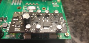
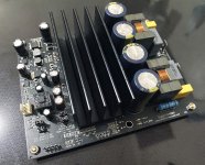
TPA3255 PBTL Prototype
PBTL Prototype in progress. No PCB mistake except for speaker out polarity label.
With 48V supply and VER2923-103KL inductors, 1kHz SINAD at 5W 4 ohms is 94dB. Clean power is up to 130W. 0.5% THD+N is 180W.
Using VER2923-682KL achieves 2dB better SINAD but clean power is only 100W. 0.5% THD+N is 140W.
Looks like TPS7A3001 is overkill so in production version I will replace the negative opamp supply regulator with LM337.
ETA in 2 months.
Attachments
- Status
- Not open for further replies.
- Home
- Vendor's Bazaar
- Amplifier Modules and PCBs For Sale