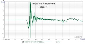
thimios, the overall uneveness of the impulse response graph is not what we expect when the measurement is done correctly. This is why Rese assumed that something is interfering with the recording of the speaker playback from the microphone. anyway, this is why you cannot properly identify the first reflection, because it is most often quit small and is hidden in the "dirty" recording. I fear we cannot really help from afar. Consider to work over your measuring setup, read-up on measuring and try to establish a clean measurment setup first. this will help you, as you can then trust your measurements.
for now, keep working with the 3 ms gate. I am not sure if your crossover works according to Rese's plans, the speaker seems to be overly bass heavy.
for now, keep working with the 3 ms gate. I am not sure if your crossover works according to Rese's plans, the speaker seems to be overly bass heavy.
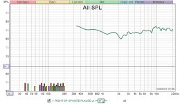
IR looks better now, but frequency response does not nearly match Rese's design goal. Maybe you need to check the crossover again.
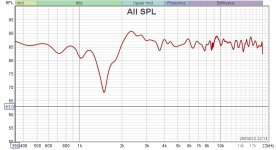
I did not study the crossover and its iterations (wasn't there a change of drivers at some time?), but from the measurements of post #7 https://www.diyaudio.com/community/threads/asathor-a-jbl-4367-clone.367215/post-6515733, the woofer in your attempt seems to roll of too fast, while the tweeter is not appropriately rolling of. Hence the V shape.
Something appears to be way off ...
Well, your measurements however show a performance that is not even close to Rese's system measurements, which were only done for the first speaker. This suggests that you should continue troubleshooting, this time for your crossover construction, once more.
Did you invert the polarity of the tweeter?
For the woofer, the line conductor ("plus") is connected to the positive terminal, whereas for the tweeter, the positive terminal receives the null wire ("minus"). so red-on-red, black-on-black for the woofer, red-on-black and black-on-red for the tweeter.
Last edited:
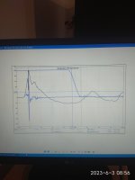
At least the tweeter response is not rising! 
If the response you posted above is the result for the inverted tweeter polarity, according to the crossover plan as per the creator, you must stick to it and solve the issue at another place. Your crossover must then contain a fundamental flaw at another level, maybe the woofer circuits.
If the response you posted above is the result for the inverted tweeter polarity, according to the crossover plan as per the creator, you must stick to it and solve the issue at another place. Your crossover must then contain a fundamental flaw at another level, maybe the woofer circuits.
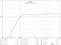
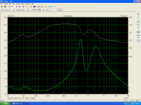
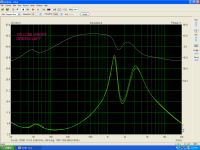
1)Horn Only,mic at a distance of 1m
2)Woofer near field 1cm.Red line with 560uf,blue line 560uf sorted
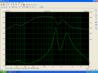
3)right speaker impedance
4)Left speaker impedance
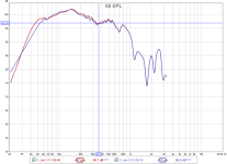
5)right,left comparison
2)Woofer near field 1cm.Red line with 560uf,blue line 560uf sorted
3)right speaker impedance
4)Left speaker impedance
5)right,left comparison
Attachments
Last edited:
Download and install VituixCad2 here https://kimmosaunisto.net/Software/VituixCAD/VituixCAD2_setup.exePlease who can help me here doing this for me?🙏
- On the other hand, sealed speakers are easy-peasy. All you need to do is measure the woofer and do baffle step correction.
Launch Diffraction tool and create your baffle. Set Sd and position of the speaker on the baffle. Set your typical listening distance (2000-3000 mm is fine). Save the project and export the response.
Open Enclosure tool, select your speaker of choice from the database and select the type of enclosure from the Align tab on the left, then load the response previously exported.

I don't understand what you're trying to do. The baffle step is already corrected in my x-over. You can also see that in your measurement of the woofer.
Please keep in mind that the baffle step is not visible in your measurement because you measured directly at the woofer. With correct measurements you would have about 5-6 decibels more between 250Hz and 1000Hz.
If you now want to correct this again, it will be considerably worse.
Please keep in mind that the baffle step is not visible in your measurement because you measured directly at the woofer. With correct measurements you would have about 5-6 decibels more between 250Hz and 1000Hz.
If you now want to correct this again, it will be considerably worse.
First, what I'm trying to do is to learn.
Second,to be shure that nothing is wrong with MY built.
It's always in DIY to know how to do it. Note that if I hadn't done the measurements I would never have discovered the mistake in the crossover due to the tweeter change.
I'm certainly not questioning your design, nor am I trying to improve it.
In the link from audiosciencereview that I had posted before, the straightforward explanation for frequency response measurements will teach you everything you need to learn for now. Including how to create a baffle step curve with the diffraction tool in Vituixcad, to adjust the woofer near field measurement in REW. This is important if you combine woofer near-field and gated far field measurements. But it is all explained in the thread and if you master the instructions, you should be right.
We cannot do the measurements for you so you need to figure this out yourself. Be sure that the microphone calibration curve is active in REW when measuring, and if you did not buy a calibrated microphone, the frequencies from 5 kHz to 20 kHz might appear elevated and with a rising tendency, so if the values of the crossover are correct, ignore this rise. Don’t change the values of the crossover.
We cannot do the measurements for you so you need to figure this out yourself. Be sure that the microphone calibration curve is active in REW when measuring, and if you did not buy a calibrated microphone, the frequencies from 5 kHz to 20 kHz might appear elevated and with a rising tendency, so if the values of the crossover are correct, ignore this rise. Don’t change the values of the crossover.
This is a good doc by @DcibeLFirst, what I'm trying to do is to learn.
https://drive.google.com/drive/folders/1P5YpzyxFulaC0JjuaSGrq4_atT42-bjU
See also this post for other interesting guides published on his drive
https://www.diyaudio.com/community/threads/vituixcad-for-newbies.391824/post-7211727
this btw is irrelevant, you don’t need to care about it. all you want is to created one proper quasi-anechoic measurement. Follow the tutorial I posted the link to in this thread twice, and you are good.Open Enclosure tool, select your speaker of choice from the database and select the type of enclosure from the Align tab on the left, then load the response previously exported.

- Home
- Loudspeakers
- Multi-Way
- Asathor - a JBL 4367 Clone