Hi Ian,
Just one question on the variable time delay the new MC FIFO will implement. Will it allow for no delay ? ie. similar to pass through?
Many thanks for your excellent product.
Abraham.
@ Abraham,
MC FIFO delay can be set to 0.1s,0.2s,04s, and 1s. Continue adjustment is also possible. I didn't design a zero delay. Because zero delay means you don't need a FIFO, and it can not work with new clock domain (old clock can not be replaced by a new clock).
Pleas let me know if you have more questions.
Regards,
Ian
Hi All,
Just a question on the 3.3v power for the clock board oscillators. I presume I dont need to implement a 3.3v regulator on the board if I am feeding the signal from external oscillator boards that already have their own 3.3 supply (ie. Well Tempered Master Clock boards)? I would obviously still power the main clock board with the 5-6Vdc but can I just leave off the 3.3V LDO reg?
On the clock board, not only XOs need 3.3V power supply, but also clock driver and re-clock section.
So, if you have external clocks, you can remove the LDO for XO, but you have to make sure other sections are also good.
Regards,
Ian
@ cyrilliu,
If you get chance watching the I2S signal from a RPi by a oscilloscope higher than 1GHz bandwidth, you will know how much the jitter that a RPi outputs is. That jitter comes from the internal audio clock generator/PLL. Has nothing to do with the buffer size. No matter how big the internal buffer is, that jitter will keep same and can not be eliminated. That's why I said RPi internal data buffer has nothing to do with sound quality. It's only has something to do with function.
FIFO is totally different story. FIFO is a data buffer between two clock domain. The goal of a FIFO is to deal with tolerances between clocks. FIFO itself doesn't improve sound quality. But with a FIFO, a poor RPi clock can be replaced by a good clock without affecting any to the music data. A poor signal is become a very high quality signal after FIFO. That the principle of FIFO.
Regards,
Ian
I get your point! It can improve the sound quality that is a high-quality clock signal for FIFO. It’s not improve if it provides a bad clock signal for FIFO.
Hi Ian
Your MC fifo looks awesome!!! Any plans to make an X-core based usb ti i2s? Then all you need is to add APM-89L « Momentum Data Systems for Atmos and DTS-X. Boom!!!
Stoff
Your MC fifo looks awesome!!! Any plans to make an X-core based usb ti i2s? Then all you need is to add APM-89L « Momentum Data Systems for Atmos and DTS-X. Boom!!!
Stoff
This is the MC FIFO finial version V6.0
MC isolator has already been integrated on board.
Ian
Ian,
Is the documentation of the set of available products available already. I followed the thread, but I am not confused a bit on all the options.
Thanks,
D.
This is the MC FIFO finial version V6.0
MC isolator has already been integrated on board.
Ian
Great design! It's better design that the output buffer is on MC Clock board because the isolator board between MC FIFO and MC clock will generates jitter, so you need to re-align the data again by the buffer on MC clock for controlling tolerances between clocks.
Last edited:
Great design! It's better design that the output buffer is on MC Clock board because isolator itself will generates jitter, so you need to re-align the data again by the buffer on MC Clock before re-clock.
Needless to say, all signals will be relocked on MC clock board.
Needless to say, all signals will be relocked on MC clock board.
Yes, you are right. Finial output buffer will be on the MC clock board.
Ian
Needless to say, all signals will be relocked on MC clock board.
Buffer and relocking are different. Buffer is to solve the tolerances between clocks. Reclcoking is for the time correction. Reclocking is no way to effectively reduce jitter from, for example, the BlackBerry pi because the tolerances between clocks.
Last edited:
Buffer and relocking are different. Buffer is to solve tolerances between clocks. Reclcoking is for the time correction.
In this case, I would say MC FIFO itself is the buffer, MC clock board has the finial re-clocking.
Ian
First, FIFO will receive the packet stored in the buffer, so even if the music signal with jitter, even each packet is much slower or much faster, and then from the FIFO output, on MC clock board through relcoker with a good clock at the right time sent the packet out to DAC.
Last edited:
First, FIFO will receive the packet stored in the buffer, so even if the music signal with jitter, even each packet is much slower or much faster, and then from the FIFO output, on MC clock board through relcoker with a good clock at the right time sent the packet out to DAC.
Frankly speaking, I don't know what you're talking about. I'd advise you going through the entire thread even from the very beginning. It's not that difficult to understand how Ian's FIFO works.
Frankly speaking, I don't know what you're talking about. I'd advise you going through the entire thread even from the very beginning. It's not that difficult to understand how Ian's FIFO works.
You can write what your understanding, let me worship it. FIFO, buffer and reclock are all not the invention of ian. They originally exist in many high-end audio equipment.
You are joking right? Unbelievable... This is not about who invent FIFO, buffer or reclock. FIFO is just a concept. The guy who "invented" the FIFO didn't even know what CD audio is. Someone needs to implement the circuit in order to work. Do your homework first and ask later.
Last edited:
You can write what your understanding, let me worship it. FIFO, buffer and reclock are all not the invention of ian. They originally exist in many high-end audio equipment.
You are joking right? Unbelievable... This is not about who invent FIFO, buffer or reclock. FIFO is just a concept. The guy who "invented" the FIFO didn't even know what CD audio is. Someone needs to implement the circuit in order to work. Do your homework first and ask later.
Hi guys,
Please just relax. Let me tell you the story of I develop the FIFO project.
I’m medical electronics and signal processing background. I’m also an audiophile for more than 30 years. I knew FIFO is the best solution to deal with jitter issue of digital audio system back to the time when I was in university. But I cannot be able to implement it until FPGA technologies became good enough.
The reason I decided to design an I2S FIFO by myself was that I couldn’t find any available FIFO solution for my DAC project at that time.
Before I started my FIFO project in 2011, the only FIFO implementation in ‘high-end audio’ was Mark Levinson No.3xx reference digital processor. It was a very excellent design. But I saw two issues of their approach.
1.The whole implement was still a concept of digital PLL with FIFO memory included. The input clock and output clock were not 100% independent from each other. The controller turns the VCXO in real-time to make it tracking lock to the input signal stream. With that small size FIFO memory delay, the cut-off frequency of that PLL could be low to two digits of Hz, but still cannot be 100% input jitter immunity.
2.It uses only VCXO as secondary master clock generator, cannot use any other kind of oscillator such as OCXO, TCXO and even XO. The customized VCXO is not only very expensive, but also limits the finial low jitter performance. Under the same condition, the phase noise of a VCXO is higher than OCXO or SC-cut XO because the control voltage.
However my implement is quite different. I designed more advanced algorithm to manage two clock domains and use much bigger FIFO memory to make the output MCLK completely isolated from input clock. It becomes a true FIFO with 100% jitter immunity from the input clock. My approach doesn’t have limitation on oscillator type. All kind of oscillators include XO, OCXO, and TCXO work for my FIFO solution up to 384KHz.
I’d like to say that I’m the first one who brought this concept into a real working ‘universal’ I2S FIFO and made it available for audio DIYer all over the world, as well as the multi-channel I2S/DSD FIFO. A lot of audiophiles had already benefited their digital audio sound quality from my FIFO project by now. I’m very proud of that.
Ian
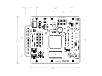
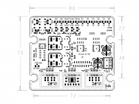
MC Dual XO update
Layout of finial version V6.0
4 MCLK outputs
4 SCK outputs
4 LRCK/D1 outputs
2 SD/D2 outputs
D3-D8 outputs
All outputs are in u.fl coaxial cable sockets only for better SI quality
Can support 4 separate DACs working at same time
Capable for 14 channels for I2S and 8 channels for DSD
0.9uV RMS/90dB PSRR/600mA ultra low noise RF LDO equipped on board for OCXO and XO
It's coming.
Ian
Attachments
Last edited:
Hi Ian,
I confirm it sounds good at home") !
!
Btw, assuming there is always a little jitter left outputing the Master Clock, did you have measured that one with the Crysteq 957 XO at the output of the clock board II ? What is the last source of residual jitter (I mean on the clean side) ? Flip/Flop chip? length of uf-l wires ?
How-much pico second jitter on the uf-l outputt plug (if possible to measure with your Tools) ?
Always wanted to ask as I have no idea of how it works : is it all the I2S signals (Bitclock, etc) which is re-clocked after the FIFO or the MCLK only (I ask because I use old PCM chips like TDA1541A...) (and sorry if the question has no sense as my understanding is low - no home work , I would even don't know where I could beginn, lol)
cheers Ian & thanks for all the amazing job
Edit : Has the MC Clock uf-l inputs plugs for the inputt side or flat cable only from the FIFO board ?
I confirm it sounds good at home
!Btw, assuming there is always a little jitter left outputing the Master Clock, did you have measured that one with the Crysteq 957 XO at the output of the clock board II ? What is the last source of residual jitter (I mean on the clean side) ? Flip/Flop chip? length of uf-l wires ?
How-much pico second jitter on the uf-l outputt plug (if possible to measure with your Tools) ?
Always wanted to ask as I have no idea of how it works : is it all the I2S signals (Bitclock, etc) which is re-clocked after the FIFO or the MCLK only (I ask because I use old PCM chips like TDA1541A...) (and sorry if the question has no sense as my understanding is low - no home work , I would even don't know where I could beginn, lol)
cheers Ian & thanks for all the amazing job
Edit : Has the MC Clock uf-l inputs plugs for the inputt side or flat cable only from the FIFO board ?
Last edited:
Hi Ian,
I confirm it sounds good at home
Btw, assuming there is always a little jitter left outputing the Master Clock, did you have measured that one with the Crysteq 957 XO at the output of the clock board II ? What is the last source of residual jitter (I mean on the clean side) ? Flip/Flop chip? length of uf-l wires ?
How-much pico second jitter on the uf-l outputt plug (if possible to measure with your Tools) ?
Always wanted to ask as I have no idea of how it works : is it all the I2S signals (Bitclock, etc) which is re-clocked after the FIFO or the MCLK only (I ask because I use old PCM chips like TDA1541A...) (and sorry if the question has no sense as my understanding is low - no home work , I would even don't know where I could beginn, lol)
cheers Ian & thanks for all the amazing job
If you input I2S, the output will be I2S. If you input DSD, the output will be DSD.
All re-clocking will be after FIFO at finial stage. The finial jitter level is now lower than the noise floor of my LC584AXL which is 3ps. So I would like to follow the specification of the XO oscillators for phase noise preference.
Ian
- Home
- Source & Line
- Digital Line Level
- Asynchronous I2S FIFO project, an ultimate weapon to fight the jitter