That is a beautiful amplifier. 300wpc @ 8 ohms X 8. 128 pounds!! Holy cow!!
It is nicely spec'd. They say explicitly that noise is wrt rated output. They also say 30 uV A weighted at the output, and gain = 28.
<0.05% up to 20kHz is not great, but who knows how much margin they are using.
Cheers,
Bob
Something smells fishy. 300W in 8ohm is 70V peak. The electrolytics in the photo are 63V.
300w could be peak power, that is 150W sine. This, I'm buying, it matches the transformer sizes, the electrolytic voltage and the number of output pairs (two each channel, apparently) and the cooling system physical size (apparently forced air).
Waly, 8 outputs on each bridged channel PCB (16 amps actually present in the box), 63 V caps are just fine. All together 64 outputs mounted in the SAE amp. ��
You may be right (I see two output coils on each board) but then 16x150W simultaneously requires 4kW of transformers. Those two transformers in the photo are max. 1kW each. Not to mention that the cooling, even forced air as it appears to be, doesn't cut it for almost 1kW of power dissipation (worst case at 4ohm).
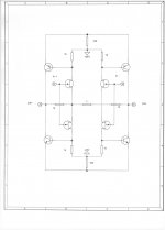
Two conventional single-ended amplifiers bridged to make a pair of opposite-polarity outputs to double the power is not a true balanced design. The guts of the amplifiers in such a case are just single-ended.
Cheers,
Bob
I will check but the purpose of my post was not to discuss a particular amp but rather raise the question as to whether "true balanced, fully differential" (to use Bob's label) deserve more airtime. Perhaps it makes it much, much easier to achieve low noise specs especially when you are building beyond stereo. (Agree the distortion isn't the best.)
I hate the way the word "pure" is used in audio discussions.
like "true"
")
Last edited:
I will check but the purpose of my post was not to discuss a particular amp but rather raise the question as to whether "true balanced, fully differential" (to use Bob's label) deserve more airtime. Perhaps it makes it much, much easier to achieve low noise specs especially when you are building beyond stereo. (Agree the distortion isn't the best.)
like "true"
"fully balanced"?
Cheers,
Bob
R.Cordell has a circuit to convert an unbalanaced input to a balanced impedance input in his interview series and I think it is also in his book.
It's just a couple of jFETs in LTP with carefully sized resistors to give the required balance of impedance.
Sorry, it's not "just", it's a carefully crafted little circuit.
It's just a couple of jFETs in LTP with carefully sized resistors to give the required balance of impedance.
Sorry, it's not "just", it's a carefully crafted little circuit.
Andrew,
Not input conversion from balanced to single ended , but fully balanced from input to output, this takes two complete ampifiers with the speaker driven by two output stages, one for the positive and one for the negative half of the signal. Carefull matching of gain determing resistors for each amplifier section is needed to acomplish it well
Not input conversion from balanced to single ended , but fully balanced from input to output, this takes two complete ampifiers with the speaker driven by two output stages, one for the positive and one for the negative half of the signal. Carefull matching of gain determing resistors for each amplifier section is needed to acomplish it well
I did not claim balanced through put for R.Cordell's little bal to unbal convertorAndrew,
Not input conversion from balanced to single ended , but fully balanced from input to output, this takes two complete ampifiers with the speaker driven by two output stages, one for the positive and one for the negative half of the signal. Carefull matching of gain determing resistors for each amplifier section is needed to acomplish it well
edited to remove an extra "a".to convert an unbalanced input to a balanced impedance input
Hi ticknpop,
Yes, exactly.
Hi SGK,
You can think of a "balanced amplifier" as a bridged connection. Instead of using the single input, inverting and amplifying that for the second amplifier, you are supplying both inputs. Of course now the onus is on your to provide the two exactly matched output signals exactly 180° out of phase with identical impedance.
The only values of using a bridged (or balanced) amplifier are reduced voltage requirements for a given power output, and it also requires less rise time to achieve the minimum needed for a signal. That shouldn't ever be an issue with a good pair of amplifier circuits. So we are down to lower supply voltages and more SOA limits to worry about as a result. I see this as an advantage only for high power output situations.
-Chris
Yes, exactly.
Hi SGK,
Yup. Things like that.like "true"
You can think of a "balanced amplifier" as a bridged connection. Instead of using the single input, inverting and amplifying that for the second amplifier, you are supplying both inputs. Of course now the onus is on your to provide the two exactly matched output signals exactly 180° out of phase with identical impedance.
The only values of using a bridged (or balanced) amplifier are reduced voltage requirements for a given power output, and it also requires less rise time to achieve the minimum needed for a signal. That shouldn't ever be an issue with a good pair of amplifier circuits. So we are down to lower supply voltages and more SOA limits to worry about as a result. I see this as an advantage only for high power output situations.
-Chris
And not using the ground rubbish tip as a reference?
FWIW a couple of snippets from an interview with Kessler:
whatever that means
FWIW a couple of snippets from an interview with Kessler:
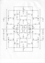
Sometime around 2007 we learned of a way to make fully balanced differential amplifiers with only a single input stage. While I didn't invent the topology, our team worked very hard to simplify the design to maintain top performance and to add ease of manufacture.
I believe the fully differential balanced design with our four-quadrant input stage and current feedback is the best way to achieve my goals.
whatever that means
A couple of things from SAE's marketing department... Yes, the amplifier is bridged.
Personally, I like drawing the distinction between a "true or pure balanced" design and a "bridged" design as Bob has done. Presumably the bridged design means a trade-off in terms of distortion as evidenced in the specs for this amp. The slew rate isn't impressive either but presumably sufficient.
As regards the size of the toroids, they didn't comment. But is it really the case that one should think of 16 x 150W as Waly wrote? Is there not efficiency to be had from the power supply as a result of the full wave rather than half wave current draw?
The input stage sounds interesting. Perhaps based at its core on the work of Barrie Gilbert?
You may be forgetting that "bridged" requires inverting one channel and summing the output. From my perspective [...] I believe that qualifiers as "full differential and balanced."
You've also uncovered one of the advantages of the balanced design which I usually summarize as, "1/2 the noise, twice the slew rate and 1/2 the operating voltage."
With the Signature amps and other Kessler designs that share the single 4-quadrant input stage we actually get 1/4 the noise.
Personally, I like drawing the distinction between a "true or pure balanced" design and a "bridged" design as Bob has done. Presumably the bridged design means a trade-off in terms of distortion as evidenced in the specs for this amp. The slew rate isn't impressive either but presumably sufficient.
As regards the size of the toroids, they didn't comment. But is it really the case that one should think of 16 x 150W as Waly wrote? Is there not efficiency to be had from the power supply as a result of the full wave rather than half wave current draw?
The input stage sounds interesting. Perhaps based at its core on the work of Barrie Gilbert?
A couple of things from SAE's marketing department... Yes, the amplifier is bridged.
The input stage sounds interesting. Perhaps based at its core on the work of Barrie Gilbert?
Good to see engineers who can't add. Noise adds as rms so it's 3dB per doubling. Not the same meaning of quadrant, I assume they are talking about full complimentary differential inputs.
Even better would be a discussion of what "true or pure balanced" gets the end user. "adds gazillion boobies to the kaboodle" isn't much use to the end user if he only uses a fraction of a boob.Personally, I like drawing the distinction between a "true or pure balanced" design and a "bridged" design as Bob has done. Presumably the bridged design means a trade-off in terms of distortion as evidenced in the specs for this amp. The slew rate isn't impressive either but presumably sufficient.
And BTW, its relatively straightforward to get 1ppm THD at 20kHz and high power with good stability and zillion V/us slew with very simple stuff like astx's excellent design.
____________________
I feel the use of "pure" should be limited to situations as God intended eg "pure Cherry". Alas unbelievers like Dave Zan insist my "pure Cherry compensation" is actually "impure"
Back to the two transistor "ring of two" current source. I can personally attest to getting into deep. deep trouble a few years ago adding a stopper to a ring-of- two source, supposing that it would be more stable that way - it took off like a scalded ape. The value might have been 100 ohms. It worked much better without, though phase margin was unknown.
I try to use depletion mode jfets/mosfets as sources when I can, with a generous stopper resistor, usually 1k. Never any problems. The one time I tried to jig up a Supertex DN2530N3 part with clip leads (and no stopper) to get a ballpark value for the source resistor, it oscillated so violently that it confused my bench supply and made a horrible racket on the FM tuner of my stereo playing on the floor above. Pretty impressive disruption for a little TO-92 part.
I try to use depletion mode jfets/mosfets as sources when I can, with a generous stopper resistor, usually 1k. Never any problems. The one time I tried to jig up a Supertex DN2530N3 part with clip leads (and no stopper) to get a ballpark value for the source resistor, it oscillated so violently that it confused my bench supply and made a horrible racket on the FM tuner of my stereo playing on the floor above. Pretty impressive disruption for a little TO-92 part.
Back to the two transistor "ring of two" current source. I can personally attest to getting into deep. deep trouble a few years ago adding a stopper to a ring-of- two source, supposing that it would be more stable that way - it took off like a scalded ape. The value might have been 100 ohms. It worked much better without, though phase margin was unknown.
I try to use depletion mode jfets/mosfets as sources when I can, with a generous stopper resistor, usually 1k. Never any problems. The one time I tried to jig up a Supertex DN2530N3 part with clip leads (and no stopper) to get a ballpark value for the source resistor, it oscillated so violently that it confused my bench supply and made a horrible racket on the FM tuner of my stereo playing on the floor above. Pretty impressive disruption for a little TO-92 part.
Was this oscillation with the DN part a result of the clip insertion or was it oscillating on it's own?
I'm sure the clip leads were a major contributing factor (as well as a dandy antenna). A 1k stopper shut it up decisively, even with the clip leads.
I found myself having to also add stoppers to the sockets in my fet sorting jig after seeing funky readings for Vgs for some parts, including some I wouldn't have normally regarded as troublesome.
I found myself having to also add stoppers to the sockets in my fet sorting jig after seeing funky readings for Vgs for some parts, including some I wouldn't have normally regarded as troublesome.
A typical 1.2V shunt reference IC has Zout < 0.5R so it makes a very excellent VREF to build a no-feedback, no-base-stopper current source
Iout = (VREF - Vbe) / Remitter.
At similar currents a stack of two series 1N4148s have Zout in the vicinity of 20-30 ohms. So the IC gives better VREF regulation, reduced parts count, and improved headroom (1.25V vs 1.40V)! I'm so wealthy I can afford to pay $0.30 for an LM4041 (link) at each and every current source if need be.
I'm so wealthy that I can afford a legacy GaAsP LED to use in a similar application. I'm lucky in that I have access to a source of NOS Litronix parts. The ones I've measured have an incremental impedance of 1.5-2 ohms, depending on bias current. They look cool, too. The LM4041 may have a lower required bias current, but I have a few thousand of the LEDs by now, and they look cool to boot.
- Home
- Amplifiers
- Solid State
- Bob Cordell's Power amplifier book