Re: Re: Re: Re: Re: Oscillation on CounterPoint
Just make it look like this and you will be fine.")
krgaunt said:
Maybe I'm not seeing something on the schematic.
RossG
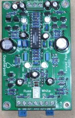
Just make it look like this and you will be fine.
Attachments
Re: Re: Re: Re: Re: Re: Oscillation on CounterPoint
I Grok! Thanks.
RossG
Russ White said:
Just make it look like this and you will be fine.
I Grok! Thanks.
RossG
Re: Re: Re: Re: Re: Re: Re: Oscillation on CounterPoint
I know it looks like crap, but it's been through prototyping mill.
krgaunt said:
I Grok! Thanks.
RossG
I know it looks like crap, but it's been through prototyping mill.
mikelm said:I'm sure that everyone else on this thread knows the relationship between a round pad, a square pad, an LED long lead, and an LED short lead - but I confess I do not . . . .
anyone care to enlighten me ?
thx
The flat side(short lead) and the square pad in this case is the cathode.
The other being obviously the anode.
Cheers!
Russ
Russ White said:The flat side(short lead) and the square pad in this case is the cathode.
hehe - actually the led's you are sending out don't have a flat side . . . but thx I got it now
NicMac said:Hi RossG,
Did changing the resistor RG1 and RG2 solve your problem? I'm experiencing something similar, but its not solved by correcting the position of RG1 and RG2.
Nic
Partially solved the problem. Running two CounterPoint boards has a lot more current draw on the power supply than the one IVY board I had running previously. The LCBPS sagged to 13 volts. So the RG1/2 resistor change also requires a power supply fix. Look on the Twisted Pair Support page under Analog/CounterPoint-IVY Stage/Connecting RG1-RG2 to GND for more details. Basically, short out the 3W resistors on the LCBPS. For the long term you might wish to consider a power supply per CP.
I did the resitor and power supply fix, but I'm getting spurious high frequency (1-2 MHz) oscillations on the output of the buffalo board and into the CP. As I pass my hand over sections of the boards I can alter the amplitued and frequency of the oscillations. If I place the palm of my hand across the two large caps on the CP board I can stop the oscillations all together. I wonder if I need to ground myself as I work around the boards?
I could have a ground loop or something's not grounded properly. I have all the panel mounted connectors isolated from the chassis. The buffalo and CP run on separate power supplies and the only ground connection between them is the gnd from the buffalo balanced outputs to the CP balanced inputs. I'll spend some more time on this problem tonight. Things would be fine if my job didn't keep interfering with my work!
RossG
NicMac said:Thanks RossG, we see the same thing/problem. Please keep me updated if you have any progress (here or on the TPA forum which I follow as well). Did you connect the AVCC of CP to 3.3V on Buffalo? I wonder if it changes anything.
Cheers,
Nic
Probably best to handle the CP stuff on our forum to help keep the traffic down here.
You both could try increasing the size of the some of the compensation caps.
Also try reducing your rails.
Cheers!
Russ
NicMac said:Did you connect the AVCC of CP to 3.3V on Buffalo? I wonder if it changes anything.
Cheers,
Nic
Yes. I connected a wire from C11 of the Buffalo to the AVCC input of my Left CP board, and a wire from C12 to the Right channel CP. The voltage on AVCC is 3.46 volts. I've had it connected this way from the start, so I've not tried to disconnect it. If there is any noise on the AVCC line my scope can't see it.
Are you getting the high freq oscillations too? To stop a possible ground loop, I'm thinking of connecting the grounds of the power supplies together and then not connect the grounds of the signal wires between the Buffalo and CP. I wonder if this is a good or dumb idea. Guess I'll find out tonight.
RossG
krgaunt said:
Yes. I connected a wire from C11 of the Buffalo to the AVCC input of my Left CP board, and a wire from C12 to the Right channel CP. The voltage on AVCC is 3.46 volts. I've had it connected this way from the start, so I've not tried to disconnect it. If there is any noise on the AVCC line my scope can't see it.
Are you getting the high freq oscillations too? To stop a possible ground loop, I'm thinking of connecting the grounds of the power supplies together and then not connect the grounds of the signal wires between the Buffalo and CP. I wonder if this is a good or dumb idea. Guess I'll find out tonight.
RossG
You have the right idea Ross.
Lets move this to the support forum please to make a long thread a little less long.

thomaspf said:Hi Russ,
thanks for posting the numbers and the graph, that looks very impressive.
One additional question. Are the numbers unweighted?
Cheers
Thomas
I forgot, could you also specify the bandwith for the distortion numbers. Is that 20-20K or 20-40Khz?
Cheers
Thomas
thomaspf said:
I forgot, could you also specify the bandwith for the distortion numbers. Is that 20-20K or 20-40Khz?
Cheers
Thomas
I believe they are A weighted. I did not measure them myself.
I already show that the measurements were at 1Khz and 20khz and I think the BW on the AP is 20-32khz.
Cheers!
Russ
NeoY2k said:Hi,
Which unit did you used to measure this DAC?
I did not measure the DAC.
I don't have access to such gear. A friend was kind enough to measure the prototype for me in exchange for early access.Cheers!
Russ
Aside from the fact that I am surprised that the moderators did not split off the technical and construction part of the threads to another area...
This is now a very long thread, can any one point me to a post of what a square wave looks like coming off the DAC, and an impulse looks like??
Thanks in advance...
_-_-bear
This is now a very long thread, can any one point me to a post of what a square wave looks like coming off the DAC, and an impulse looks like??
Thanks in advance...
_-_-bear
bear said:Aside from the fact that I am surprised that the moderators did not split off the technical and construction part of the threads to another area...
This is now a very long thread, can any one point me to a post of what a square wave looks like coming off the DAC, and an impulse looks like??
Thanks in advance...
_-_-bear
None have been posted yet.
Cheers!
Russ
- Status
- This old topic is closed. If you want to reopen this topic, contact a moderator using the "Report Post" button.
- Home
- More Vendors...
- Twisted Pear
- Buffalo DAC (ESS Sabre 9008)