Ouch. Maybe it is worth to check how much will be shipping from the Audiophonics?price after shipping from UK for small quantity (~$46/pair!!)
https://www.audiophonics.fr/en/composants-electronique-transistors-puces-c-512.html
Just a remainder, “select grade” laterals are not P to N part matched at all and there is no reason not to order cheaper non-binned ones.
The binning is for paralleling them I believe. Matching n to p means adding some gate-source capacitance to match those up so the drivers see a symmetrical load, although I'm not sure its worth it as many circuits have the gates shorted to each other at AC anyway, and the internal capacitances are very non-linear anyway (its a MOS capacitor basically).
I think double-die devices are already bin-matched so that's going to be cheaper than matched single dies.
I think double-die devices are already bin-matched so that's going to be cheaper than matched single dies.
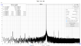
Member @mislaaav nudged me to check the TMC compensation with this amplifier, as he is working on his own version of similar design, that has a TMC compensation.
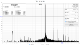
I’ve checked two pole (TPC), transitional Miller (TMC) and three pole which is a combination of TPC+TMC. Those compensation methods bring, in real circuit, some 6 – 12 db lower distortion (20 dB in simulation). For now, TMC seems the best choice as it provides the same unconditional stability as a standard Miller compensation.
Result are just a little better numbers, nothing more. Sound is, of course, exactly the same. It should be, as we are taking about distortion that is, to start with, one millionth part of the output signal.
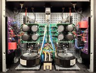
I took the chance to rearrange parts like with @cibo build.") With only 300 mm deep case, using two separate ground loop breaker circuits instead of one dual, enables better PS placement.
With only 300 mm deep case, using two separate ground loop breaker circuits instead of one dual, enables better PS placement.
I’ve checked two pole (TPC), transitional Miller (TMC) and three pole which is a combination of TPC+TMC. Those compensation methods bring, in real circuit, some 6 – 12 db lower distortion (20 dB in simulation). For now, TMC seems the best choice as it provides the same unconditional stability as a standard Miller compensation.
Result are just a little better numbers, nothing more. Sound is, of course, exactly the same. It should be, as we are taking about distortion that is, to start with, one millionth part of the output signal.
I took the chance to rearrange parts like with @cibo build.
With only 300 mm deep case, using two separate ground loop breaker circuits instead of one dual, enables better PS placement.Attachments
Hi tombo 56,
A friend suggested this thread, which I read entire with great interest. I found you design extremely interesting and I'm thinking of building it in the not so far future.
I have a couple of questions:
Evangelos
A friend suggested this thread, which I read entire with great interest. I found you design extremely interesting and I'm thinking of building it in the not so far future.
I have a couple of questions:
- How is the gain calculated? In particular, all my amplifiers are in the 20dB level and I would like this to have the same gain. How can I increase the amplification factor?
- I have always been an advocate of 0 NFB school. Is there a way to eliminate feedback in your design?
Evangelos
Hi Evangelos,
as everything after the opamp is a voltage follower output stage, gain is determined by opamp NFB divider ratio (R4+R5+R6 / R3) +1. Equals 4x or 12 dB.
When considering amplifier’s gain, we have to check required gain structure. With low output of some 15V peak, there is no need for 20 dB gain, especially if there is some preamplifier in the chain. Even direct drive from DAC is fine for some 8W/8Ω output.
Increasing gain also increases slightly distortion, noise and output impedance. As all those values were measured to be extremely good, no issues there. If it’s absolutely necessary, gain can be increased by changing R3 to lower value. I wouldn’t go past 17 dB (R3 = 750Ω). Quick check with simulation shows that amplifier stability would remain the same, but such matters need to be checked with real circuit and conditions.
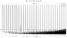
When discussing NFB, I understand your point. My previous amplifier was with zero NFB, but this one is by numbers and sound-wise better in every way. There is nothing detrimental by NFB with modern high bandwidth amplifiers, just the opposite. Look at the 31 tone distortion. It looks as something measured directly at the top performance DAC output.
Removing NFB would completely ruin performance and doesn’t have any sense for this circuit.
It is true that, > 30 years ago, when bad designs were ‘improved’ by high NFB, result was good distortion number at 1 kHz only, and bad sound.
Cheers,
Boris
as everything after the opamp is a voltage follower output stage, gain is determined by opamp NFB divider ratio (R4+R5+R6 / R3) +1. Equals 4x or 12 dB.
When considering amplifier’s gain, we have to check required gain structure. With low output of some 15V peak, there is no need for 20 dB gain, especially if there is some preamplifier in the chain. Even direct drive from DAC is fine for some 8W/8Ω output.
Increasing gain also increases slightly distortion, noise and output impedance. As all those values were measured to be extremely good, no issues there. If it’s absolutely necessary, gain can be increased by changing R3 to lower value. I wouldn’t go past 17 dB (R3 = 750Ω). Quick check with simulation shows that amplifier stability would remain the same, but such matters need to be checked with real circuit and conditions.
When discussing NFB, I understand your point. My previous amplifier was with zero NFB, but this one is by numbers and sound-wise better in every way. There is nothing detrimental by NFB with modern high bandwidth amplifiers, just the opposite. Look at the 31 tone distortion. It looks as something measured directly at the top performance DAC output.
Removing NFB would completely ruin performance and doesn’t have any sense for this circuit.
It is true that, > 30 years ago, when bad designs were ‘improved’ by high NFB, result was good distortion number at 1 kHz only, and bad sound.
Cheers,
Boris
Last edited:
Hi Boris,
Thank you for your response.
Regarding negative feedback, I also thought that there might be stability issues with this design, since it has a very wide frequency response, rising up to 1.3 MHz. So, I will abandon that thought.
As to increasing gain, I think I will start with your values and, if I consider that I need more gain, I could readily change R3.
My speakers are quite sensitive (97dB/1W horns), hence 5-6 Watts is more than enough for me (in fact, in my "armamentarium", I have a 2 Watt tube amplifier that sounds great). So, I was thinking of biasing output MOSFETs at 0.7-0.8 A.
Best regards,
Evangelos
- Home
- Amplifiers
- Solid State
- Building an ultimate low power class A amplifier – my way