D
Deleted member 548388
Hi folks,
I just signed up at diy audio hoping to find some help.
Back in late 2020 I replaced all the electrolytic capacitors of my SRM-006t and added CCS to it. Later I went for ECC99 tubes, following the advices given in this thread and the german blog that somebody posted a link to some pages back. Everything went well and sounded brilliant with my lambdas.
This year I traded my modded 006t for a used SRM-007t, adjusted the input voltage and replaced all electrolytic capacitors. A few months later I successfully performed the rather comprehensive work for it to take 6S4A tubes. Based on my experience with CCS, I decided to add this feature to my 007t as well. That's where I'm struggling currently.
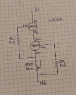
I'm using the same schematic for the CCS that I've been using for my SRM-006t. This get's closest to what I use: http://blog.prof-x.de/wp-content/uploads/2018/08/20180804_CSS_JimL1.jpg I replaced the unlabeled resistor by a 500R trimpot.
Of course, this time I adjusted the outputs to 8.0mA each. For some reason I keep frying the fets in my CCS. Parts were purchased from Mouser, I would consider them genuine. First I though this was a temperature issue, but even when using massive heat sinks on the 10M90S, both fets (10M90S and DN2540) keep failing, from time to time. By failing I mean, that one or both fets in each cascade seem to lose the ability to restrict the current flow, leading to way too high CCS output currents up to 20mA (instead of 8 what each CCS is being adjusted to). Of course, the power supply can't provide that amount of current without B+ dropping. My current working hypothesis is that the gates of one or both fets of each CCS get damaged, either during power-up of the amp or after switching power off. 10M90S are hard to find, and I'm in urgent need of a solution for this so that I don't keep frying them. Unfortunately, I'm not able to tell which fet "goes south" first in case of a failure.
I was given the advice to use Dale resistors which I did, but didn't help solve the issue.
Does anybody have an idea about how to fix this? Any help is highly appreciated.
I just signed up at diy audio hoping to find some help.
Back in late 2020 I replaced all the electrolytic capacitors of my SRM-006t and added CCS to it. Later I went for ECC99 tubes, following the advices given in this thread and the german blog that somebody posted a link to some pages back. Everything went well and sounded brilliant with my lambdas.
This year I traded my modded 006t for a used SRM-007t, adjusted the input voltage and replaced all electrolytic capacitors. A few months later I successfully performed the rather comprehensive work for it to take 6S4A tubes. Based on my experience with CCS, I decided to add this feature to my 007t as well. That's where I'm struggling currently.
I'm using the same schematic for the CCS that I've been using for my SRM-006t. This get's closest to what I use: http://blog.prof-x.de/wp-content/uploads/2018/08/20180804_CSS_JimL1.jpg I replaced the unlabeled resistor by a 500R trimpot.
Of course, this time I adjusted the outputs to 8.0mA each. For some reason I keep frying the fets in my CCS. Parts were purchased from Mouser, I would consider them genuine. First I though this was a temperature issue, but even when using massive heat sinks on the 10M90S, both fets (10M90S and DN2540) keep failing, from time to time. By failing I mean, that one or both fets in each cascade seem to lose the ability to restrict the current flow, leading to way too high CCS output currents up to 20mA (instead of 8 what each CCS is being adjusted to). Of course, the power supply can't provide that amount of current without B+ dropping. My current working hypothesis is that the gates of one or both fets of each CCS get damaged, either during power-up of the amp or after switching power off. 10M90S are hard to find, and I'm in urgent need of a solution for this so that I don't keep frying them. Unfortunately, I'm not able to tell which fet "goes south" first in case of a failure.
I was given the advice to use Dale resistors which I did, but didn't help solve the issue.
Does anybody have an idea about how to fix this? Any help is highly appreciated.
Do you have some pictures of how your CCS are built? Also I recommend 1K gate stopper for the DN2540 - I have had oscillation problems with that part in some instances. Are the stopper resistors mounted right at the gate? How are the devices mounted to the heat sinks?
I have been using a very similar circuit for over a decade without any failures in lots of stuff. If you are using a trim pot in the source of the DN2540 make sure it is a sturdy one that can dissipate the required power., I would recommend shunting it with another resistor so that if the pot goes open your mosfet does not blow up.
Can you share a hand drawn schematic of your exact implementation?

D
Deleted member 548388
Thanks for approving my first thread and for your quick reply, Kevin.
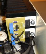
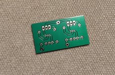
I took some pictures of the CCS in the amp, the back of the PCB and my hand drawn schematic as requested. Please excuse the rather low quality.... the 500R pot is rated at 500mW.
Of course I adjusted and tested the CCS at about 30V DC prior to integrating it into the amp.
I took some pictures of the CCS in the amp, the back of the PCB and my hand drawn schematic as requested. Please excuse the rather low quality.... the 500R pot is rated at 500mW.
Of course I adjusted and tested the CCS at about 30V DC prior to integrating it into the amp.
Attachments
Last edited by a moderator:
D
Deleted member 548388
Obviously, what I did is a blatand rip-off of what KG, Spritzer, JimL, and so many others have been doing for years.
Still, I'm having a hard time understanding the root cause of the defects I keep facing. Would it be possible that I just caught a bad batch of semiconductors or pots?
Still, I'm having a hard time understanding the root cause of the defects I keep facing. Would it be possible that I just caught a bad batch of semiconductors or pots?
D
Deleted member 548388
D
Deleted member 548388
@Jeff Yourison: May I ask you to expand on this a bit? For this specific application I haven't seen Zeners being used, still no reports of failures whatsoever. That's exactly what keeps bugging me ")
@Lingwendil: Failures occur after hours or even days of use with several power cycles in between. I wasn't able to isolate any defect pattern.
@Lingwendil: Failures occur after hours or even days of use with several power cycles in between. I wasn't able to isolate any defect pattern.
I lost about a bunch of DN2540 in several PSUs around 300..350V, usually at power up.
It was "upper" device of cascode CCS on appropriate heatsink.
Since then I started using in HV CCS 1kV Ixys depletion FETs (mainly IXTP01N100) in this position and none of them destroyed.
Nowadays I use DN2540 as "lower" and IXTP (01N100 .. 08N100) as upper FET (see #3 post).
It was "upper" device of cascode CCS on appropriate heatsink.
Since then I started using in HV CCS 1kV Ixys depletion FETs (mainly IXTP01N100) in this position and none of them destroyed.
Nowadays I use DN2540 as "lower" and IXTP (01N100 .. 08N100) as upper FET (see #3 post).
Last edited:
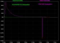
In SY's "ImPasse" balanced preamplifier I have used a pair of DN2540's -- the TO-220 flavor. You have two different devices with two different gate capacitances so it may be that they are charging at different rates.
FWIW, I have had the Ixys devices fail in a Pete Millett "Engineers Amp"
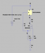
Here's a little simulation of the dissipation in each device at turn-on:
FWIW, I have had the Ixys devices fail in a Pete Millett "Engineers Amp"
Here's a little simulation of the dissipation in each device at turn-on:
Attachments
Are you read Ale Moglia (here mogliaa https://www.diyaudio.com/community/members/mogliaa.120717/) site?
https://www.bartola.co.uk/valves/for-sale/ccs-pcb/
https://www.bartola.co.uk/valves/for-sale/ccs-pcb/
D
Deleted member 548388
It is strange that the DN2540 often burns out. I have been using them for more than 10 years without zener diodes and none of them have burned out even with 5W dissipation (250V voltage drop, 20mA). Two DN2540 should be rock solid, but I'm not sure about the 10M90S and DN2540.
I would perhaps opt for another CCS because it is obvious that the combination of 10M90S and DN2540 has some problem.
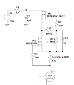
Below is the schematic of the CCS I used in my tube DAC, it is much better than other combinations and has one useful addition, a voltage multiplier for the lower mosfet.
I would perhaps opt for another CCS because it is obvious that the combination of 10M90S and DN2540 has some problem.
Below is the schematic of the CCS I used in my tube DAC, it is much better than other combinations and has one useful addition, a voltage multiplier for the lower mosfet.
Attachments
It's a turn-on pulse to see how much energy is being dissipated by both devices. The TO-92 version of the DN2540 can only sustain milliwatts of energy.@jackinnj: What scenario are the dissipation graphs reflecting?
Don't overlook the trimmer. The wiper can fail, particularly when it is used at the ends.
Details in this app note:
https://www.bourns.com/docs/technic...-notes/bourns_wiper_setting_apno.pdf?sfvrsn=0
Details in this app note:
https://www.bourns.com/docs/technic...-notes/bourns_wiper_setting_apno.pdf?sfvrsn=0
D
Deleted member 548388
It is strange that the DN2540 often burns out. I have been using them for more than 10 years without zener diodes and none of them have burned out even with 5W dissipation (250V voltage drop, 20mA). Two DN2540 should be rock solid, but I'm not sure about the 10M90S and DN2540.
I would perhaps opt for another CCS because it is obvious that the combination of 10M90S and DN2540 has some problem.
I wouldn't say it's flawed "obviously", considering there's hundreds out there in e.g. KG designs that have been working like a charm for ages. Keep in mind, I don't know if the DN2540 dies as a result of the 10M90S failing or vice versa.
Using the heatsink in the image, temperature of the 10M90S maxes out at below 70°C with the amp's lid closed of course.
The energy dissipation aspect might be interesting. The guy I copied the PCBs and BOMs from explained to me he made hundreds of single CCSs and none of them failed ever.
Thank you so much for the discussion, folks, I appreciate it a lot!
In your experience, how likely is a component issue from the factory (DN2540, 10M90S, Pot, PCB) vs. an implementation issue (lead lengths, tracing, etc.)?
- Home
- Amplifiers
- Tubes / Valves
- CCS keeps failing