
@ItsAllInMyHead
I have been a DIY slacker of recent. Hate it when life, work, etc get in the way of some DIY fun. That being said, your recent build updates have me totally motivated to get my Randy Aleph 30 built. I have all the boards, parts, donuts, etc. Need to get the chassis ordered which is where I stalled last time. I have actually built up 2 V8 PSU boards already. Used 50V 380LX 22k uF for 1st 2 C and then 50V 380LX 33k uF for the last 2 C. I am starting with the Aleph 30 but can totally envision it morphing into the 60 (already have those boards, fets also).
I had questions:
1: Do you have any other pictures of how you incorporated the Hammond chokes into the V8 boards? Looking at the schematics and applying my limited knowledge my best guess is you just leave R1, R2, R3, and R4 unpopulated and then wire the Hammonds across R1 and R3? I have read more than once ZM wax poetic about the use of chokes vs R and this seems like a very slick way to incorporate them into Randy's boards. And sense I haven't put anything into a chassis yet pretty easy to adapt into my builds.
2: I believe you covered this in the other thread about a universal outboard PS thread but was there an issue just using the PowerCon connectors similar to what Pass uses on the XS 150 and 300 amps to connect the umbilicals? Seem like the DC voltage for the XS amps should exceed anything we are playing with, even building out an Aleph 2. While I believe my Aleph 30/60 builds will be single chassis I love the idea of an universal Pass DIY PS setup for the standard DIY amp power requirements. Ideally one chassis PS and separate Left and Right channel chassis with something like M2X and SissySIT both installed. Want to switch amps, just switch input/output and PS input then go. What I had envisioned is exactly what you have executed to an even higher standard. Cudos!
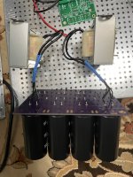
Chokes - take a wire and bend it into a U shape to create a loop. Connect the holes of R1&R2 and R3&R4. Connect the choke wires to those U / Loops. The red lines are the loops you'll create. Top side or bottom side, up to you. Use the thicker gauge scrap wire from 3W resistors that are coming off the main aleph boards or other wire that fits in the holes.

Last edited:
^ Well, that's certainly high praise. Thank you. I'm thrilled.
FWIW... if you have the chassis, and you know you're going to do the 60, I'd just start there. If you don't have the chassis, then 30 to 60 seems perfectly natural. I just know that I am a lazy beast. Once something finds its way hooked into the system, I am rarely motivated to yank it back out. You may be far more diligent.
Onto your actual questions.
1. You are correct re: wiring. Pic attached of my first effort. The choke wires are a much larger diameter than the holes. So, I thought I would be clever and split them into two pieces attached to some 18AWG solid core which fit perfectly into the PCBs. I'd strongly advise against the way I first did it... The chokes are heavy, and I'm ham-fisted. The solid core snapped twice after repeated strain as I was monkeying around with layouts. So... I took everything apart and redid it using some really flexible multi-strand. Worked like a champ. With that said... I know for a fact that others (with far more knowledge and talent) have better attachment methods; drilling out the PCB, and/or bundling the choke wires and 'necking them down' to fit into the smaller holes. Also... while I would never commit someone else's time... Randy is a pretty darn nice guy, if you asked... he may have a way to mod the boards to make it easier to use chokes. What I don't know is how to measure (properly) if the connections are proper. I'm 99% sure that they are. Measuring a 0R16 resistance with my DMM is sketchy at best, and the circuit "works" without them in place. It seems to measure well from a noise standpoint. So, I consider it good. If you know of a tip re: how to measure that they're actually wired properly, I'd love to know. Can inductance be measured in situ? Maybe some reading for me.
2. Nope. Not an issue. It was me overthinking things and likely causing a lot of confusion for myself and others. With that said, I will repeat the words of the Neutrik engineer with whom I spoke. He said (paraphrased) - I would not use those connectors for that application (meaning my specific application). The only product of ours I would recommend for that application are the XLR connectors.
So, I am not encouraging or discouraging the use of any type or form factor of connector. I simply don't know enough.
I love your vision. I hope to see it realized in pictures throughout the threads.")
Edited to add - See Randy simul posted with an answer re: how better to do it.
FWIW... if you have the chassis, and you know you're going to do the 60, I'd just start there. If you don't have the chassis, then 30 to 60 seems perfectly natural. I just know that I am a lazy beast. Once something finds its way hooked into the system, I am rarely motivated to yank it back out.
You may be far more diligent.Onto your actual questions.
1. You are correct re: wiring. Pic attached of my first effort. The choke wires are a much larger diameter than the holes. So, I thought I would be clever and split them into two pieces attached to some 18AWG solid core which fit perfectly into the PCBs. I'd strongly advise against the way I first did it... The chokes are heavy, and I'm ham-fisted. The solid core snapped twice after repeated strain as I was monkeying around with layouts. So... I took everything apart and redid it using some really flexible multi-strand. Worked like a champ. With that said... I know for a fact that others (with far more knowledge and talent) have better attachment methods; drilling out the PCB, and/or bundling the choke wires and 'necking them down' to fit into the smaller holes. Also... while I would never commit someone else's time... Randy is a pretty darn nice guy, if you asked... he may have a way to mod the boards to make it easier to use chokes. What I don't know is how to measure (properly) if the connections are proper. I'm 99% sure that they are. Measuring a 0R16 resistance with my DMM is sketchy at best, and the circuit "works" without them in place. It seems to measure well from a noise standpoint. So, I consider it good. If you know of a tip re: how to measure that they're actually wired properly, I'd love to know. Can inductance be measured in situ? Maybe some reading for me.
2. Nope. Not an issue. It was me overthinking things and likely causing a lot of confusion for myself and others. With that said, I will repeat the words of the Neutrik engineer with whom I spoke. He said (paraphrased) - I would not use those connectors for that application (meaning my specific application). The only product of ours I would recommend for that application are the XLR connectors.
So, I am not encouraging or discouraging the use of any type or form factor of connector. I simply don't know enough.
I love your vision. I hope to see it realized in pictures throughout the threads.
Edited to add - See Randy simul posted with an answer re: how better to do it.
Attachments
So what came of the Aleph 40? It looks like @AddiDub made an Aleph 35'ish. I am surprised that the 5u chassis has a hard time handling 40 watts where as a monoblock it can handle 100w. There must be something that I am missing.
It seems like the aleph 40 would be a nice boost to the Aleph 30 while still being able to be installed in a single chassis. Not too much extra cost either.
Anyone have any thoughts?
It seems like the aleph 40 would be a nice boost to the Aleph 30 while still being able to be installed in a single chassis. Not too much extra cost either.
Anyone have any thoughts?
Chokes - take a wire and bend it into a U shape to create a loop. Connect the holes of R1&R2 and R3&R4. Connect the choke wires to those U / Loops. The red lines are the loops you'll create. Top side or bottom side, up to you. Use the thicker gauge scrap wire from 3W resistors that are coming off the main aleph boards or other wire that fits in the holes.
View attachment 1203554
Now that’s a simple solution! Pretty sure I’m going to give it a try, don‘t see a downside. The Hammond chokes are not that expensive, I think with a 5U chassis there should plenty of room.
Maybe I missed it, did you find some sockets for the input Fets? I have to dig through the parts box but I think ended up with 4 different pair including turning up a pair of 2SJ313. Sounds like a great idea if it doesn’t compromise performance.
^ Well, that's certainly high praise. Thank you. I'm thrilled.
FWIW... if you have the chassis, and you know you're going to do the 60, I'd just start there. If you don't have the chassis, then 30 to 60 seems perfectly natural. I just know that I am a lazy beast. Once something finds its way hooked into the system, I am rarely motivated to yank it back out.
Onto your actual questions.
1. You are correct re: wiring. Pic attached of my first effort. The choke wires are a much larger diameter than the holes. So, I thought I would be clever and split them into two pieces attached to some 18AWG solid core which fit perfectly into the PCBs. I'd strongly advise against the way I first did it... The chokes are heavy, and I'm ham-fisted. The solid core snapped twice after repeated strain as I was monkeying around with layouts. So... I took everything apart and redid it using some really flexible multi-strand. Worked like a champ. With that said... I know for a fact that others (with far more knowledge and talent) have better attachment methods; drilling out the PCB, and/or bundling the choke wires and 'necking them down' to fit into the smaller holes. Also... while I would never commit someone else's time... Randy is a pretty darn nice guy, if you asked... he may have a way to mod the boards to make it easier to use chokes. What I don't know is how to measure (properly) if the connections are proper. I'm 99% sure that they are. Measuring a 0R16 resistance with my DMM is sketchy at best, and the circuit "works" without them in place. It seems to measure well from a noise standpoint. So, I consider it good. If you know of a tip re: how to measure that they're actually wired properly, I'd love to know. Can inductance be measured in situ? Maybe some reading for me.
2. Nope. Not an issue. It was me overthinking things and likely causing a lot of confusion for myself and others. With that said, I will repeat the words of the Neutrik engineer with whom I spoke. He said (paraphrased) - I would not use those connectors for that application (meaning my specific application). The only product of ours I would recommend for that application are the XLR connectors.
So, I am not encouraging or discouraging the use of any type or form factor of connector. I simply don't know enough.
I love your vision. I hope to see it realized in pictures throughout the threads.
Edited to add - See Randy simul posted with an answer re: how better to do it.
Nice to see I wasn’t the only one confused about the PowerCon. I know they suggested an XLR connection, I would have the same hesitation as you, especially in an amp that has XLR line level inputs. 4 XLRs on the back seems like a recipe for accidental disaster. I have a 5M run from the Pre to Amps that is balanced/XLR, certainly would not want someone to accidentally plug a PS XLR umbilical into a XLR line level input, with 3 kids between 6-12 those concerns are real.
Totally agree about just building the Aleph 60 from the beginning but I don’t have one of those fancy 4U500 chassis, would need to do it as monoblocks. Just going to order up 2 5U deluxe chassis, one for Aleph 30 and another for trying M2X and SissySIT.
Now if anyone has one of those 4U500 chassis they want to sell, let me know, will grab some bigger donuts and go big from the beginning. Don’t think I ”need” the power of the Aleph 60 but never hurts if you want to turn it up to 11.
Try these sockets, they're on my newest Aleph 30's.
https://www.amazon.com/gp/product/B09MYMD4YS/ref=ppx_yo_dt_b_search_asin_title?ie=UTF8&th=1
I was going to put some in an envelope and send them to you, but let's just say my spare parts boxes could use some organization... Semis and resistors are in good order, the rest are pure chaos.
The sockets are somewhere in the house, that much I know.
Last edited:
A few question arose while I was comparing the input stages of the different (2, 3, 4, 5, 30 and 60) models of Aleph amplifiers. I have attached the relevant parts of the Aleph 3 and Aleph 30 schematics (copied from the service manuals).
I have read the manuals and think I understand the changes in the (input network) resistor values, additional 10pF capacitor parallel to (what I presume is the feedback) resistor, but why is the feedback resistor (marked with a red circle) 100k in all models except the Aleph 3 (where it is 10k)?
I have read the manuals and think I understand the changes in the (input network) resistor values, additional 10pF capacitor parallel to (what I presume is the feedback) resistor, but why is the feedback resistor (marked with a red circle) 100k in all models except the Aleph 3 (where it is 10k)?
Attachments
After a delay working on another project ... at long last I finally had a chance to get back to my Aleph 60 for a little while. It's still not done... but I wanted to do a few measurements before I buttoned it up. These are (as the title in a few of the graphs say) playing around. I don't even remember the bias I originally set. I just got it hot...
The AC Gain is 50% by the method described in the guide. For those that like measurements... here ya go! I thought it was pretty cool that the 1% distortion point was... you guessed it ... 60W (8R).
Note... I am just getting familiar with measurements. So, take these with a bucket of salt. They make sense, so I'm posting them. I also ensured a high level of repeatability. I trust them, but ... you may not. If I find any errors as I learn more, I'll certainly say something. tl;dr - they're correct to the best of my knowledge and ability.
I am tickled to death with the "Wretched Excess" PSU and the A60. I had to "go deep" to try and find any 60Hz and harmonics. It's quiet.
In no particular order.... Thank you to:
@rhthatcher - You DA MAN!
@Extreme_Boky and @TungstenAudio - I took all the teachings to heart. I am still not sure that I completely understand it all ...
@Zen Mod the Mighty and the ever-guiding and kind @6L6 for keeping a fella like me between the ditches...
@Ben Mah and @Dennis Hui for measurement guidance and just being awesome.
Last, but not least - @Nelson Pass -
I'm sure I've unintentionally left someone out. Apologies. I've been inspired (stolen ideas shamelessly) from so many people.
I'll post pics once I've done some prettying up. The last pics posted are pretty much the way it still looks.
And... the best measurement of all... it sounds awesome!
I still want to play with AC gain etc... but that will come later.
Here's the noise floor. Yep... it's quiet...

Here's the Power vs THD...

Some 8R distortion measurements. The 2nd Harmonic (negative) is prevalent throughout the power range.


And a few at 4R


More to come... I've had a blast building and learning as I go with this project.
Thanks to all!


The AC Gain is 50% by the method described in the guide. For those that like measurements... here ya go! I thought it was pretty cool that the 1% distortion point was... you guessed it ... 60W (8R).
Note... I am just getting familiar with measurements. So, take these with a bucket of salt. They make sense, so I'm posting them. I also ensured a high level of repeatability. I trust them, but ... you may not. If I find any errors as I learn more, I'll certainly say something. tl;dr - they're correct to the best of my knowledge and ability.
I am tickled to death with the "Wretched Excess" PSU and the A60. I had to "go deep" to try and find any 60Hz and harmonics. It's quiet.
In no particular order.... Thank you to:
@rhthatcher - You DA MAN!
@Extreme_Boky and @TungstenAudio - I took all the teachings to heart. I am still not sure that I completely understand it all ...
@Zen Mod the Mighty and the ever-guiding and kind @6L6 for keeping a fella like me between the ditches...
@Ben Mah and @Dennis Hui for measurement guidance and just being awesome.
Last, but not least - @Nelson Pass -
I'm sure I've unintentionally left someone out. Apologies. I've been inspired (stolen ideas shamelessly) from so many people.
I'll post pics once I've done some prettying up. The last pics posted are pretty much the way it still looks.
And... the best measurement of all... it sounds awesome!
I still want to play with AC gain etc... but that will come later.
Here's the noise floor. Yep... it's quiet...
Here's the Power vs THD...
Some 8R distortion measurements. The 2nd Harmonic (negative) is prevalent throughout the power range.
And a few at 4R
More to come... I've had a blast building and learning as I go with this project.
Thanks to all!

Nice drawings... thanks.
Did you push into 4 ohms?
The Aleph 60 published specs are: 60 watts/ch @ 8 ohms, 100 watts @ 4 ohms @ 1% THD
By comparison, the Aleph 5 is spec'd at 1 % @ 60 watts, 8 ohms 3% @ 90 watts, 4 ohms
No wonder @rhthatcher prefers his 60s over my 5s. ;-)
Now, what kind of speakers are you gonna drive with it.
See above. What do you mean by push? I didn't take it to 100W, but high enough for me.Did you push into 4 ohms?
I have a few sets of speakers... the Tekton DIs are attached at the moment. The Vandersteen 3As are getting a workover... then they'll get a try. The Vandy's were a gift from my wife 23 years ago on Saturday... So, I'm trying to tweak them a bit and see if they can earn their spot in the line.
- Home
- Amplifiers
- Pass Labs
- Classic Aleph Amplifier for Modern UMS Chassis Builder's Thread